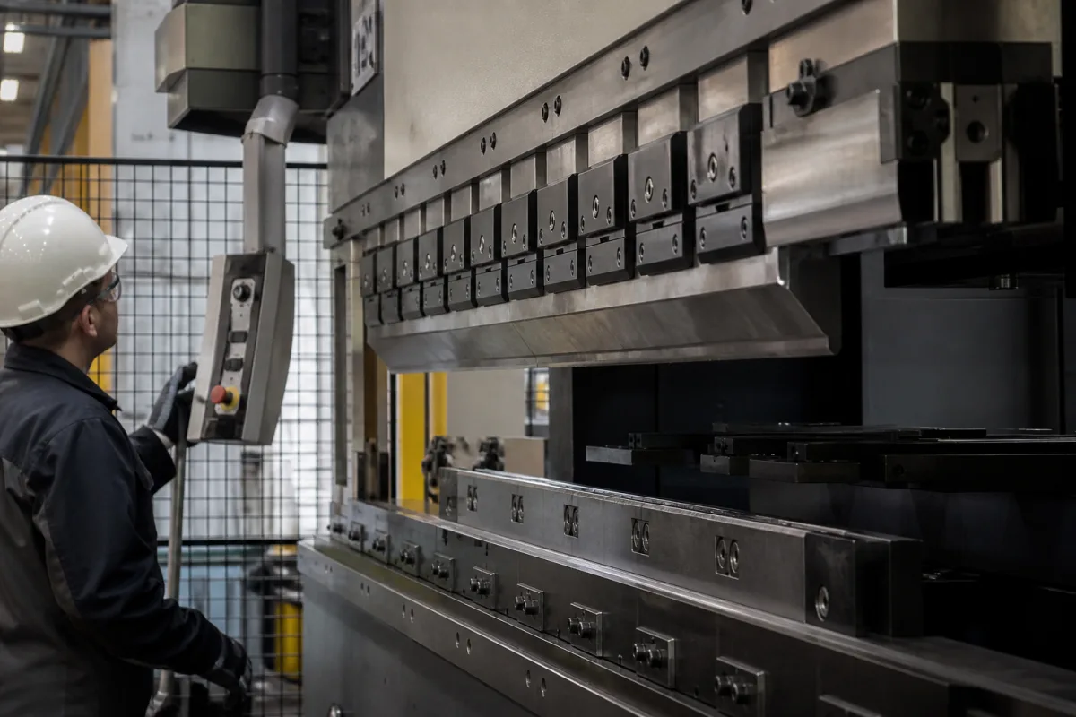
Press brake ram (upper beam) driven by Y1/Y2 cylinders: end-to-end synchronisation, speed profile and parallelism
The moving upper beam of a hydraulic press brake and the two cylinders that drive it · keeping both ends level to a few microns, the approach–bend–return speed profile, the 10 mm/s safe-speed limit, and beam-to-table parallelism at acceptance
On a hydraulic press brake the ram is the heavy upper beam that holds the punch. It is pushed down by two cylinders, one at each end (the Y1 and Y2 axes), and its job is to arrive at exactly the same depth along the whole bend line, at a speed that is fast when nothing is in the way and slow when a hand could be. How the two ends are kept level, how the speed changes over the stroke and how the beam's alignment is checked at acceptance decide whether the ram bends the same angle at both ends of a part.
The ram (upper beam, press beam) of hydraulic and servo-hydraulic press brakes and its Y1/Y2 cylinder drive: synchronisation of the two ends, approach, working and return speeds, stroke, daylight, speed monitoring, and the beam's parallelism and perpendicularity. Press brake selection, bending force and guarding as a whole are covered on the Hydraulic press brake page; tool holders and clamps fitted under the ram on the Ram punch holder (intermediate and clamp) for press brakes page; punches and V-dies on the V-die set page; in-process angle measurement on the CNC press brake with angle measurement page; thick-plate bending presses and their crowning on the Heavy plate bending press page. The CNC console, axis boards and valve outputs that command Y1 and Y2 are on the CNC control system for press brakes page, which counts the axes; this page deals with the beam's mechanical and hydraulic behaviour. Servo-pump stamping presses are on the Precision hydraulic stamping press page.
CNFX editorial research · Sources checked October 12, 2026 · 4 sources
Two cylinders, one beam: holding Y1 and Y2 level to about 0.0002 in
Cincinnati Inc.'s patent US 4,797,831 starts from the fault it fixes: when the two cylinders do not track each other exactly, one end of the ram and its punch sits higher than the other, the reversal point is wrong at one end, and that end of the workpiece is bent differently. [1]
The patented control fits a position encoder at each end of the ram that gives one pulse per 0.0001 in of travel, or 10,000 pulses per inch. Each end's pulse count is compared with a digital reference proportional to the desired ram speed, and the resulting error is added to the speed command for that cylinder's valve. Under steady-state conditions the two ends differ by no more than ±2 pulses, about 0.0002 in. [1] Editorial conversion: 0.0001 in is 2.54 µm, so ±2 pulses is about ±5 µm.
The same principle, two independently controlled ends measured by their own scales, is what a modern purchase specification asks for when it names an optical or magnetic linear scale for the Y-axis and a Y1–Y2 beam-tilting feature. [2] Tilting is deliberate: the controller can run the ends at different depths to compensate for a tapered part, which only works if each end is controlled on its own measurement.
Ask how each end of the ram is measured (linear scale or encoder, resolution), how far the ends may differ in steady state, and whether the control can tilt the beam on purpose.
02
Approach fast, bend slow, return fast: the ram's speed profile and the 10 mm/s limit
A ram stroke has three speeds. CSIR-CMERI's specification for a 2,500 mm, 1,000 kN NC press brake states them as a minimum, with higher speeds quotable as options:
Rockford Systems, a safeguarding supplier, explains where the slow speed comes from: the 2012 revision of ANSI B11.3 added a safe-speed method, drawn from Europe's EN 12622, under which the closing ram must be automatically monitored so that it does not exceed 10 mm/s and is stopped if it does. It applies when the light curtain is muted for the bend, and Rockford notes it is limited to hydraulic (and potentially servo-drive) press brakes. [3]
Editorial calculation: the CMERI working speed of 5 mm/s is half the 10 mm/s safe-speed limit, while its 30 mm/s approach is three times it, so the approach must end, or the light curtain must still be active, before the punch reaches the opening where fingers could be. Over the full 150 mm stroke, approach at 30 mm/s would take 5 s and return at 60 mm/s 2.5 s. The specification gives the stroke as 150 mm in one item and the Y-axis stroke control as 200 mm in another; a bidder would need to confirm which figure is meant.
Amada's patent US 7,036,345 B2 describes how such a speed can be monitored on a pump-driven ram: one speed is taken from the ram position detector, a second is computed from the servo motor's speed and the pump's displacement, and if the two differ by a set amount the servo motor is stopped at once, so a failed ram sensor cannot go unnoticed. [4]
Adjustable stroke; optical or magnetic linear scale; Y1–Y2 beam tilting [2]
03
Checking the beam at acceptance: parallelism, perpendicularity and bend results
CSIR-CMERI makes the ram's alignment an acceptance criterion at pre-despatch inspection, citing DIN 55222 Class I or an IMTMA equivalent. [2]
The same specification asks for bend tests on the maker's standard test piece before despatch and at least five different test pieces at commissioning, inspected for dimensional tolerance, and for a manual crowning system. [2] Editorial note: the parallelism figure is static geometry; the Y1/Y2 synchronisation in the first section is what keeps the beam parallel while it moves under load, so ask for both.
State the acceptance standard (for example DIN 55222 class), beam-to-table parallelism and stroke perpendicularity, the Y-axis accuracy, and the test pieces to be bent before despatch.
04
What to specify for a press brake ram and its drive
Paste it into your enquiry below or into an email to a maker, then replace every bracket.
Beam: [bending length; distance between columns; throat]
Drive: [Y1/Y2 cylinders; force per cylinder; hydraulic or servo-pump]
Measurement: [linear scale per end; resolution; steady-state end difference]
Speeds: [approach / working / return mm/s; safe-speed monitoring]
Geometry: [stroke; daylight]
Acceptance: [parallelism; perpendicularity; Y accuracy; test pieces]
Explore company information and manufacturing capabilities, then discuss the scope of your project with a relevant supplier.
Share this page
Compiled and source-reviewed by the CNFX editorial team.
Each manufacturer above links to the page on that company's own website where the product is listed, with the date we checked it. How we source and review
· Page last updated 13 October 2026
Buyer questions
What are Y1 and Y2 on a press brake?
The two ends of the ram, each driven by its own cylinder; Cincinnati's US 4,797,831 controls each from its own encoder to keep them within about 0.0002 in. [1]
How fast does a press brake ram move?
A CSIR-CMERI purchase specification asks for at least 30 mm/s approach, 5 mm/s working and 60 mm/s return. [2]
What is safe speed on a press brake?
Per Rockford Systems, ANSI B11.3 (2012) allows a monitored ram closing speed of 10 mm/s or less, stopped if exceeded, drawn from EN 12622. [3]
How is press brake ram alignment checked?
CSIR-CMERI specifies 50–100 µm beam-to-table parallelism per 2,500 mm and 60–100 µm perpendicularity per 150 mm of stroke. [2]
Sources and what still needs a direct check
Sources checked 2026-10-12. Synchronisation comes from Cincinnati Inc.'s US patent 4,797,831 and speed monitoring from Amada's US 7,036,345 B2; speeds, geometry and acceptance values from a CSIR-CMERI purchase specification; the safe-speed limit from Rockford Systems' account of ANSI B11.3 and EN 12622.