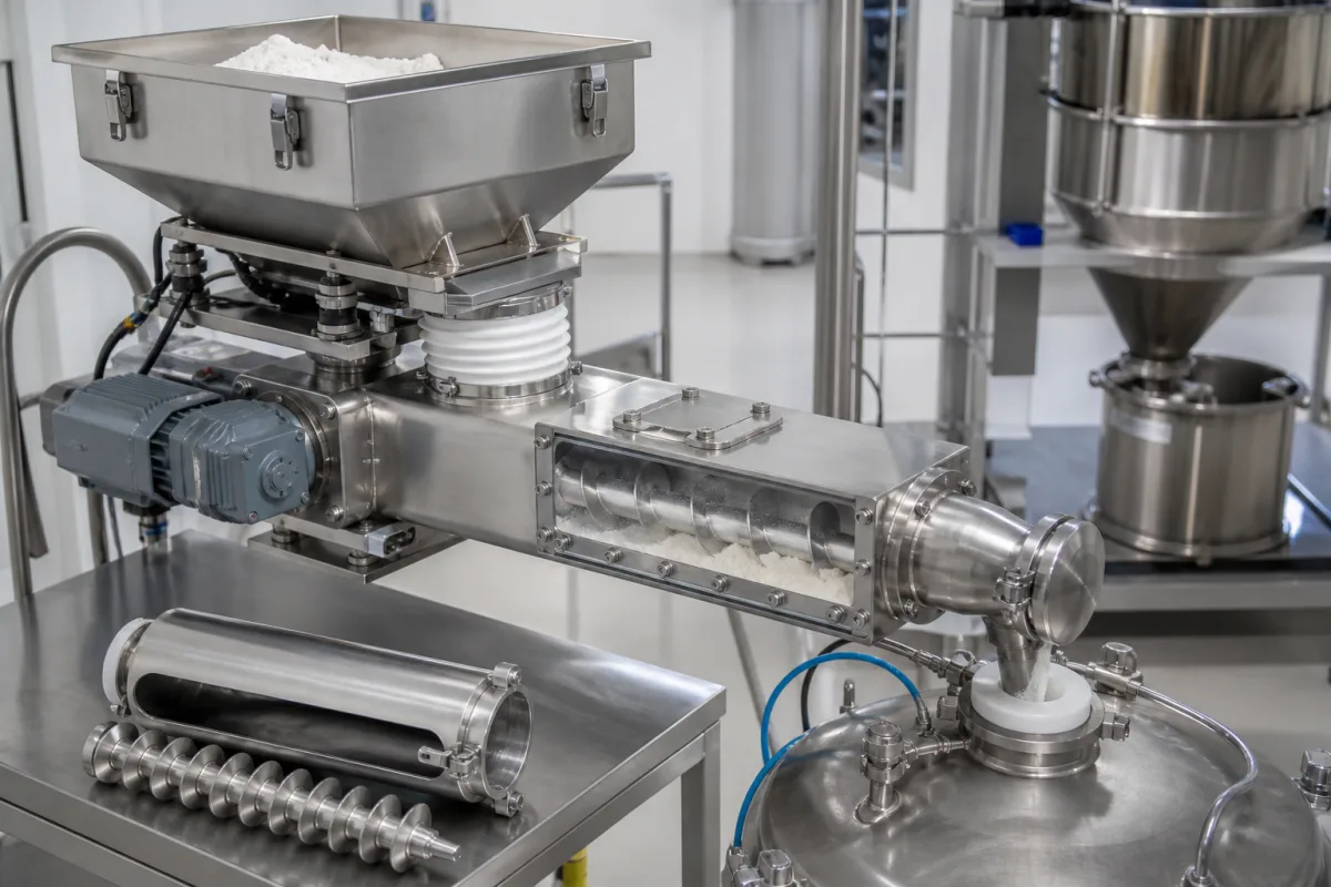
Bulk solids · Even drawdown from the hopper, control pitch and speed, start-up torque and shroud length
A screw feeder meters powders and granules from a hopper, bin or silo using a rotating screw under a flood-loaded inlet. Ask three things first: how the screw draws material evenly from the whole inlet, the feed-rate range and the speed and control pitch that set it, and the drive torque needed to start under a full hopper.
Screw (auger) feeders for bulk powders and granules, single, twin and live-bottom, horizontal or inclined, volumetric or as part of a weighing system. Automatic screw feeders that present fasteners to screwdrivers, vibratory bowl feeders and screw conveyors used only for transport are outside this page.
CNFX editorial research · Sources checked October 11, 2026 · 4 sources
Design the screw for even drawdown from the hopper
KWS Manufacturing's engineering guide says a screw feeder's inlet is always flood loaded, so the screw design in the inlet and the screw speed set the feed rate. It does not recommend a uniform-diameter, constant-pitch screw, because material fills the screw from the rear of the inlet first, creating rat-holing, stagnant material and bridging; each flight must add volume toward the discharge, using variable or stepped pitch, a tapered outside diameter, or a mass-flow design developed by Jenike & Johanson. [1]
The guide adds that "most screw feeders are less than 20-feet in length" because internal hanger bearings are not recommended, that a shroud must extend at least 2 pitches beyond the inlet to stop flooding, and that live-bottom feeders with multiple screws draw material evenly from large openings for materials that pack or bridge. Inclined feeders lose efficiency above 5° and need material testing. [1]
Give the supplier the material and its flow behaviour, loose and packed bulk density, particle size, moisture and temperature, minimum and maximum feed rate, hopper or silo outlet size, accuracy needed, incline, hygiene or wash-down requirements and whether the feeder is part of a weighing system.
02
Set the feed rate, speed and drive
KWS defines the control pitch as the last flight entering the shroud; its capacity per revolution sets the feed rate, and screw speed equals the maximum capacity divided by the control pitch's capacity per rpm. KWS says that in heavy industrial applications screw feeders "typically operate at speeds less than 20-RPM". Horsepower and torque are much higher than for a comparable conveyor because the feeder starts with a flood-loaded inlet and the head load of material above it; the material factor can exceed 4.0 for packed materials and start-up power and torque can be 2.5 times normal operation. Variable-speed drives improve metering accuracy and widen the feed-rate range. [1]
Editorial calculation: a feeder that needs 3 kW running could need about 2.5 × 3 = 7.5 kW at start-up. [1] The 3 kW figure is illustrative; ask suppliers for running and start-up torque at your material and hopper head.
Brightsail's packing-line screw feeder lists a 100–230 L hopper, 1–20 m³/h capacity and 20–140 rpm. Editorial calculation: that is a 20:1 range in capacity against a 7:1 range in speed, so the published range spans screw sizes; ask for the rate per rpm of the screw offered. [2]
03
Screw feeders for packing lines, mineral plants and feed mills
Brightsail lists screw feeders for powder and granule packing lines; Xianfeng lists auger feeders with sieves and conveyors; JXSC lists twin screw feeders for mineral processing; Juli lists screw feeders with stackers and conveyors; Deci lists screw feeders for animal-feed plants; Xuyi Titan lists fabricated screw feeders and conveyors.
04
Decide between volumetric and loss-in-weight control, and screw type
Coperion K-Tron's technical paper on feeder cost explains that a volumetric screw feeder sets a volume per unit of time by screw speed, so its accuracy depends on the uniformity of the material's flow and its bulk density. A loss-in-weight (LIW) feeder weighs the hopper and adjusts screw speed to hold a feed rate in weight per time, compensating for density changes. The paper adds that if material bridges or rat-holes, an LIW feeder detects the missing weight loss, while a volumetric feeder keeps running at its set speed and may deliver little or no material for a period. [3]
On screw type, the paper states that intermeshing co-rotating twin screws form sealed, forward-moving pockets that act like a positive displacement pump and self-wipe, while single screws are not recommended for floodable, cohesive or poor-flowing materials. It cites screw feeders feeding at rates as low as 20 g/h with screws as small as 12 mm in diameter. [3]
For LIW feeders, it advises checking weighing resolution, control response and the warranted temperature range, and warns that hopper vibrators can disturb the weight signal unless the control filters it. For product-contact parts in the pet food plants it covers, it gives a minimum 0.8 micron Ra finish on 316 or 316L stainless steel, and notes that finishes below 0.2 micron Ra may impede flow rather than improve it. [3]
05
Limit screw length under the outlet and screw speed
J.W. Carson of Jenike & Johanson, writing in bulk solids handling (2000), says uniform discharge over a hopper outlet is achieved by combining increasing pitch with a decreasing-diameter conical shaft, but that with normal fabrication tolerances, extending the screw under the outlet to "greater than about six to eight times the screw diameter often results in a poorly performing screw"; special designs such as a stepped-shaft, variable-pitch screw extend this length. [4]
He advises limiting rotational speed to no greater than about 40 rpm to prevent significant abrasive wear or excess power requirements, and adds: "Low rpm's (2 or less) often require large, expensive reducers." He says internal hanger bearings should not be used, since "a typical screw feeder operates in the range of 90 to 100% full throughout most of its length". For close control he points to gravimetric feeders: "Typically this means requiring a feed rate uniformity of better than about ±2%, or sample collection times of less than about 30 sec." [4]
Editorial calculation: for a 300 mm screw, six to eight diameters is 1.8–2.4 m under the outlet (0.3 m × 6; 0.3 m × 8).
06
Screw, inlet, shroud, trough and drive of a flood-loaded feeder
Part
Role
Fix in the order
Screw
Variable pitch, tapered or mass-flow for even drawdown. [1]
Screw design and material.
Inlet
Matches the bin or hopper outlet; flood loaded. [1]
Screw diameter, rate per rpm, speed range and start-up power for a feeder order
Three rows carry published figures: Brightsail's 1–20 m³/h range, KWS's heavy-duty speed quote and its 2.5× start-up factor. Screw diameter, IP rating, contact materials and mass come from the offer for your material.
6 companies list this product among what they make. Company figures are quoted from each
company's own website; every card states where the relationship came from.
Brightsail Industries Group Co.,Ltd.
Manufacturing site to be confirmed for the order
Lists screw feeders for powder and granule packing lines.
Explore company information and manufacturing capabilities, then discuss the scope of your project with a relevant supplier.
Share this page
Compiled and source-reviewed by the CNFX editorial team.
Each manufacturer above links to the page on that company's own website where the product is listed, with the date we checked it. How we source and review
· Page last updated 13 October 2026
Buyer questions
Why does a constant-pitch screw feeder cause rat-holing?
Material fills the screw from the rear of the inlet first; variable pitch, tapered or mass-flow screws are needed to draw evenly. [1]
How fast do screw feeders run?
KWS says that in heavy industrial applications screw feeders "typically operate at speeds less than 20-RPM"; speed equals capacity divided by the control pitch's capacity per rpm. [1]
How much extra power is needed at start-up?
KWS says start-up horsepower and torque can be 2.5 times normal running. [1]
When is a loss-in-weight screw feeder worth it over a volumetric one?
Coperion K-Tron's technical paper says a volumetric feeder's accuracy depends on uniform flow and bulk density, while a loss-in-weight feeder weighs the hopper, compensates for density changes and detects bridging or rat-holing by the missing weight loss. [3]
How long can a screw feeder inlet under the hopper be?
J.W. Carson of Jenike & Johanson writes in bulk solids handling that, with normal fabrication tolerances, more than about six to eight screw diameters under the outlet "often results in a poorly performing screw" unless special designs such as a stepped-shaft, variable-pitch screw are used. [4]
Sources and what still needs a direct check
Sources checked 2026-10-11. KWS Manufacturing is a screw conveyor and feeder maker; its engineering guide is its own. Brightsail is a supplier listed on this page.