Editorial Technical Reference

Drive Unit

This page explains how Drive Unit is classified within Machinery and Equipment Manufacturing. Technical values and manufacturer relationships are research references; confirm the current specification and supplier evidence for each order.

Technical Definition & Core Assembly

A mechanical assembly that provides the motive power to move a conveyor belt or chain within a conveyor section.

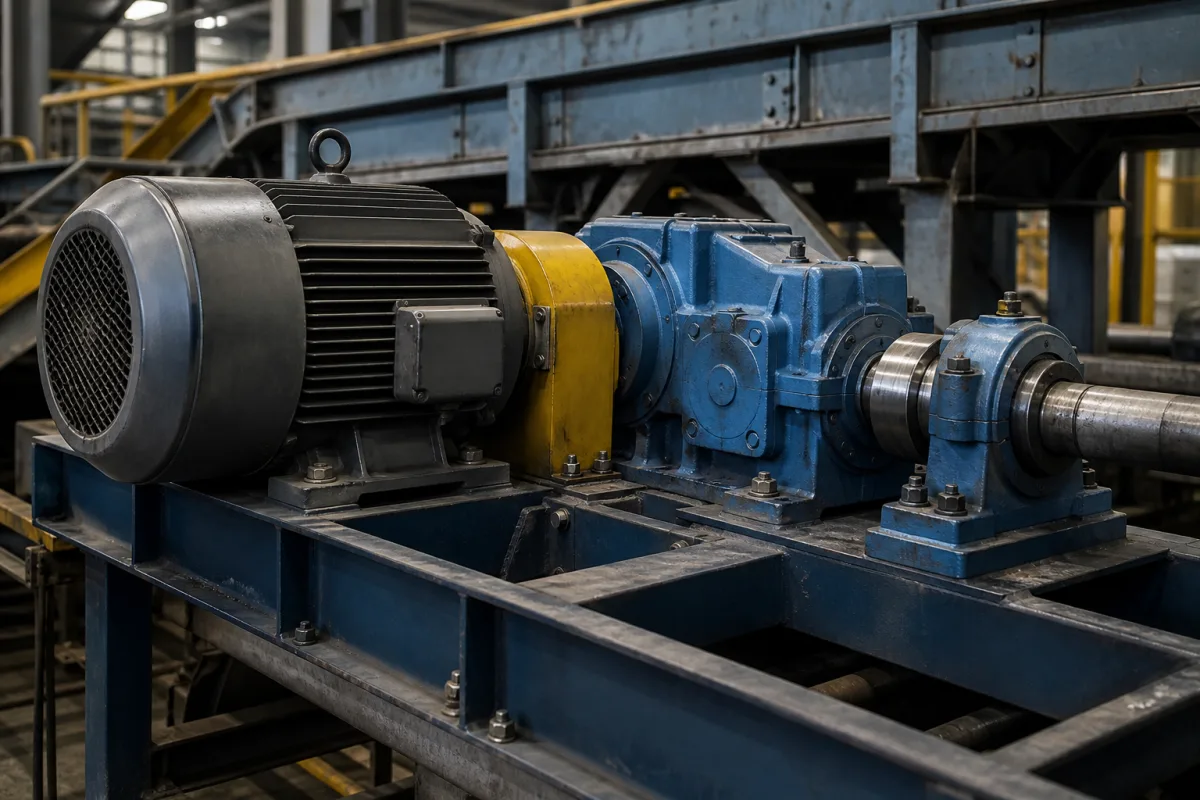
Representative product image. Confirm appearance and specifications with the manufacturer.

Product Specifications

Technical details and manufacturing context for Drive Unit

Definition
The drive unit is the core power transmission component of a conveyor section, responsible for converting electrical or mechanical energy into controlled linear motion to transport materials along the conveyor. It typically consists of a motor, gearbox, and drive pulley/sprocket assembly, and is critical for setting the conveyor's speed, torque, and operational reliability. This directory entry covers drive units used in belt and chain conveyors within machinery and equipment manufacturing. The unit's rated power ranges from 0.75 to 7.5 kW, with output speeds from 0.5 to 2.5 m/s, and torque from 100 to 500 N·m. Gear ratios from 5 to 100 are available, and efficiency is at least 92% at full load. Supply voltage is 380–480 V AC, three-phase, 50/60 Hz, and the unit is VFD compatible. Ambient temperature range is -20 to 40°C, with derating above 40°C. Protection class is IP55 to IP65, and noise level does not exceed 75 dB(A) at 1 meter. Weight ranges from 50 to 250 kg, and mounting positions M1 to M6 are supported. Materials used include cast iron, carbon steel, and alloy steel. These values are reference ranges; actual specifications must be confirmed with the manufacturer for the specific model and application. The drive unit is selected based on belt load and speed, and the gearbox ratio determines output speed and torque. It is designed for dusty or wet environments with appropriate IP ratings. Always verify model-specific values and standards with the legal manufacturer or supplier before procurement.
Working Principle
An electric motor (often AC induction or geared motor) provides rotational power. This rotation is transmitted, usually at a reduced speed and increased torque via a gearbox or speed reducer, to a drive shaft. The drive shaft is connected to a drive pulley (for belt conveyors) or sprocket (for chain conveyors), which engages with the conveyor belt or chain. Friction (belt) or positive engagement (chain) between the drive surface and the conveyor medium creates the pulling force necessary to move the load.
Common Materials
Cast Iron, Carbon Steel, Alloy Steel
Technical Parameters
ParameterTypical rangeNotes & selection driver
Rated Power0.75–7.5 kWSelect based on belt load and speedIEC 60034-1
Output Speed0.5–2.5 m/sAdjustable via gearbox ratio
Torque100–500 N·mPeak torque for starting and overload
Gear Ratio5–100Determines output speed and torqueISO 6336
Efficiency≥92 %At full loadIEC 60034-2-1
Supply Voltage380–480 V ACThree-phase, 50/60 HzIEC 60038
Frequency50–60 HzVFD compatibleIEC 60038
Ambient Temperature-20–40 °CDerate above 40°CIEC 60034-1
Protection ClassIP55–IP65IP65 for dusty/wet environmentsIEC 60529
Noise Level≤75 dB(A)At 1 m distanceISO 1680
Weight50–250 kgDepends on power and gearbox
Mounting PositionM1–M6Any orientationIEC 60034-7

Ranges are indicative industry figures for RFQ preparation, not a supplier commitment. Confirm every value and standard with the legal manufacturer before ordering.

Components / BOM
  • Electric Motor
    Converts electrical energy into rotational mechanical energy.
    Material: Laminated Steel, Copper Windings
  • Gearbox / Speed Reducer
    Reduces the motor's high speed to a usable output speed while increasing torque.
    Material: Cast Iron Housing, Alloy Steel Gears
  • Drive Shaft Part
    Transmits the reduced rotation from the gearbox to the drive pulley or sprocket.
    Material: Carbon Steel or Alloy Steel
  • Drive Pulley/Sprocket
    The final component that interfaces with and drives the conveyor belt or chain.
    Material: Steel, sometimes with rubber lagging (pulley)
  • Mounting Frame/Bedplate Part
    Provides a rigid structure to align and secure all drive unit components.
    Material: Structural Steel

Applied To / Applications

This component is essential for the following industrial systems and equipment:

Industrial Ecosystem & Supply Chain Structure

Complementary Systems
Downstream Applications
Specialized Tooling

Application Fit & Sizing Matrix

Operational Limits
pressure: N/A (mechanical drive unit)
other spec: Max Torque: 500 Nm, Speed Range: 0-100 RPM, Duty Cycle: Continuous
temperature: -20°C to 80°C
Media Compatibility
✓ Dry bulk materials (grains, aggregates) ✓ Packaged goods (boxes, containers) ✓ General manufacturing components
Unsuitable: Corrosive chemical environments without proper sealing
Sizing Data Required
  • Required conveyor load capacity (kg/m)
  • Belt/chain speed (m/s)
  • Total conveyor length and incline angle

Reliability & Engineering Risk Analysis

Failure Mode & Root Cause
Bearing fatigue failure
Cause: Inadequate lubrication leading to metal-to-metal contact, contamination ingress, or excessive loading beyond design limits causing subsurface cracks and spalling.
Gear tooth pitting and wear
Cause: Misalignment-induced uneven load distribution, improper backlash setting, or contaminated lubricant causing surface degradation and progressive material loss.
Maintenance Indicators
  • High-frequency metallic screeching or grinding noises during operation indicating bearing degradation or gear mesh issues
  • Visible oil leaks around seals or housing with metallic particles in lubricant samples (shiny flakes in oil)
Engineering Tips
  • Implement condition-based lubrication using oil analysis to monitor viscosity, contamination levels, and wear particle concentration rather than fixed time intervals
  • Install laser alignment tools during assembly and perform quarterly alignment checks with thermal growth compensation to prevent premature gear and bearing failures

Indicative industry ranges for design and RFQ preparation. Confirm the exact figures and applicable standard with the manufacturer before specifying.

Compliance & Manufacturing Standards

Applicable Standards
ISO 1940-1:2003 (Mechanical vibration - Balance quality requirements for rotors in a constant (rigid) state) ANSI/AGMA 2000-A88 (Gear Classification and Inspection Handbook) DIN 3962 (Tolerances for cylindrical gear teeth)

Quoted from the published standard.

Manufacturing Precision
  • Shaft runout: +/-0.01mm
  • Gear tooth profile deviation: +/-0.005mm
Quality Inspection
  • Vibration analysis for imbalance and misalignment
  • Hardness testing (Rockwell C scale) on gear teeth and bearings

Manufacturers of Drive Unit

3 companies list this product among what they make. Company figures are quoted from each company's own website; every card states where the relationship came from.

China Harmonic Drive (CHD®)
Shanghai, CN
Listed on the company's own website · profile compiled by CNFX from public sources
Shanghai Michigan Machinery Co., Ltd.
Shanghai, CN
Listed on the company's own website · profile compiled by CNFX from public sources
Sovonex
Tianjin, CN
Listed on the company's own website · profile compiled by CNFX from public sources

Manufacturer listings support early research and capability understanding. They are not certification, ranking, or transaction guarantees.

Technical documentation
Request current drawings, revision history, and a signed specification sheet.
Manufacturing capability
Verify equipment lists, process limits, capacity, and representative production evidence.
Inspection readiness
Confirm test methods, calibrated equipment, sampling plans, and traceable reports.
Supplier transparency
Check the legal entity, factory address, ownership, certifications, and direct contacts.

CNFX does not score or rank suppliers. Buyers must verify all claims and documents with the legal manufacturer before ordering.

Supply Chain Compatible Machinery & Devices

Automated Powder Coating System

Integrated industrial system for applying dry powder coatings to metal substrates.

Explore Specs →
Centrifugal Pump Impeller

The centrifugal pump impeller is a critical rotating component that converts mechanical energy from the motor into kinetic energy in fluid systems.

Explore Specs →
High-Precision CNC Laser Cutting Machine

Computer-controlled industrial machine using focused laser beams to cut sheet metal with micron-level accuracy.

Explore Specs →
Industrial-Grade Hydraulic Cylinder Piston Rod

This industrial-grade piston rod is a precision-ground cylindrical component designed for use in hydraulic cylinders.

Explore Specs →

Frequently Asked Questions

What is the typical power range for this drive unit?

The rated power range is 0.75 to 7.5 kW, but the exact value depends on the belt load and required speed. Always confirm with the manufacturer for your specific application.

Can the output speed be adjusted?

Yes, the output speed is adjustable via the gearbox ratio. The standard range is 0.5 to 2.5 m/s, but the actual speed depends on the gearbox selected and the motor speed.

What protection class is available?

The drive unit is available with protection classes IP55 to IP65, suitable for dusty or wet environments. The required IP rating should be specified based on the operating conditions.

What standards apply to this drive unit?

Relevant standards include IEC 60034-1 for motors, IEC 60034-2-1 for efficiency, IEC 60038 for voltage, IEC 60529 for protection, ISO 6336 for gear rating, and ISO 1680 for noise. These are reference standards; compliance must be verified with the manufacturer.

Data Basis

Editorial classification, named public sources where available, and source-reviewed manufacturer records.

Preliminary Technical Classification
This page supports structured research, RFQ preparation, and supplier evaluation. It does not replace buyer-led supplier qualification, standards review, or technical approval.
Buyer enquiry

Request manufacturing insight for Drive Unit

Ask for use case, specification boundaries, supplier type, and RFQ preparation information for this product.

Where it goes
Straight to the CNFX editorial desk, and to the manufacturer if this product is linked to a claimed profile. Nothing is broadcast to a supplier list.
Your details stay here
We do not sell or rent enquiry data, and we do not add you to a mailing list. Used only to answer this request.
No commission, no middleman
CNFX is a directory. We take no cut of any order and never negotiate on a supplier's behalf.
What we don't claim
A listing is not an endorsement. Qualify every supplier and verify every figure yourself before ordering.

Your business information is used only to process this request.

Thank you! Your message has been sent. We'll respond within 1–3 business days.
Sorry, we couldn't send your message. Please try again, or email us at contact@cnfx.com.

Need to Manufacture Drive Unit?

Compare manufacturer profiles with relevant product and process capability.

Previous Product
Z-axis Ram/Spindle
Last Product
Get QuotesChat