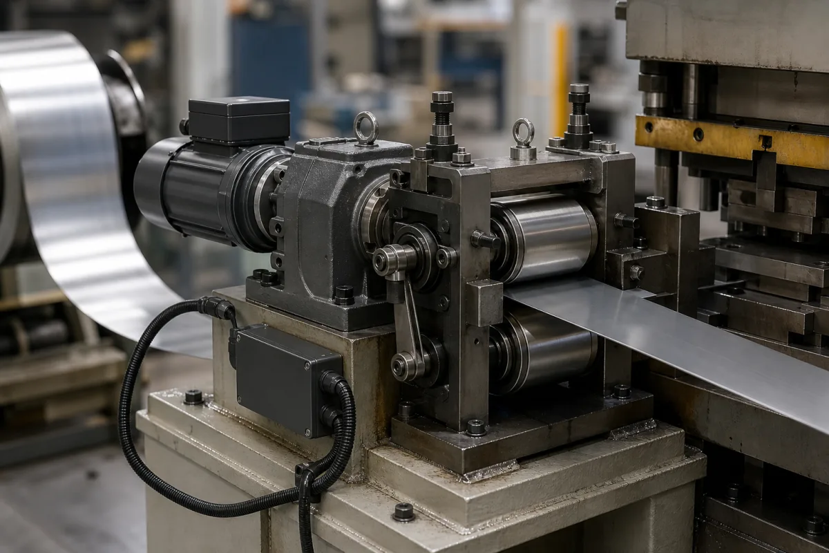
Press coil feeding · Feed window and crank angle, pilot release timing, feed length, speed and accuracy
A servo feeder (servo roll feeder or NC servo feeder) advances metal strip from a coil into a press die by a programmed length each stroke, using feed rolls driven by a servo motor. Ask three things first: how much of each press stroke is available for feeding at your speed, how the rolls release the strip for the die pilots and how fast, and what feed accuracy the supplier states for your material.
Servo-driven roll feeders for stamping presses, including NC servo feeders and combined straightener-feeders, for metal strip from coil. Air feeders, gripper feeders without rolls, bulk-material screw feeders and vibratory part feeders are outside this page.
CNFX editorial research · Sources checked October 11, 2026 · 4 sources
US patent 4,032,056 (priority 1975) explains that strip may be fed only while the pilot punch and stroke punch are clear of the material, which with a conventional crank drive is from 270° through 0° to 90° of crankshaft rotation. It notes that these start and stop points are where the ram reaches maximum speed, so feeds driven through conventional transmissions apply large inertia to the rolls and strip there, risking slippage and poorer feed accuracy. [1]
Editorial calculation: at 60 strokes per minute each stroke takes 1 s, so a 180° window (270°–90°) leaves 0.5 s for the feed; a 100 mm feed then needs an average strip speed of 0.2 m/s, or 12 m/min. At 120 strokes per minute the same feed needs 24 m/min on average. The peak speed of the roll motion profile is higher than the average. [1]
Editorial note: the actual window depends on the die height, pilot length and press stroke, so ask the die designer for the crank angles at which the strip must start and finish moving, then check that the feeder's stated speed and acceleration fit that time.
Give the supplier the press type, stroke and strokes per minute, the feed window in crank degrees, feed lengths (including multi-step feeds), strip width, thickness and material, coil weight, and whether a straightener is combined with the feeder.
02
Time the pilot release for your press speed
Coe Press Equipment's US patent 11,130,165 (priority 2018) explains that the feed rolls must open so die pilots can align the strip, and must regain their grip before the die releases it as it opens. It calls pneumatic or hydraulic cylinders "the most commonly used method of feed roll clamping control" and says they have a combined delay of 0.04 to 0.2 seconds. At 60 strokes per minute a 0.1 s delay puts the release or clamp 36° of crank rotation late, and at 100 strokes per minute 60° late. The consequences include strip damage, bad parts, damage to tooling and short feeding. [2]
The patent describes advancing the release signal by the speed-dependent lag, and replacing the cylinders with a servo motor driving eccentric cams that open the rolls and can sense the material to compensate for thickness. [2] Editorial calculation: lag in degrees = delay (s) × strokes per minute × 6, so 0.04 s at 100 strokes per minute is 24° and 0.2 s is 120°.
The older mechanical design in US 4,032,056 does the same with a lift cam timed to the crankshaft: the rolls separate immediately before the pilot punch contacts the strip, leaving the strip free to be set in position by the pilot, and a brake stops the driven roll from turning on by inertia. [1]
03
Compare what suppliers offer
Suppliers linked to this page list servo roll feeders for presses; each card links to the page reviewed.
Stated feed accuracies vary in form: Etone gives ±0.03 mm for closed-loop models, Keyadi up to ±0.1 mm, Sunrui ±0.15 mm, and Qiaosen ±0.15 mm per metre. Ask how each figure is measured and over what feed length.
04
Check thickness capacity at full width and the basis of rated speed
Rapid-Air's servo feed model table shows that thickness capacity is stated at full width and falls as width rises within one series. In its 200T series the 208T (8 in, 203 mm) takes .105 in (2.66 mm) at full width, the 212T (12 in) .095 in (2.41 mm), the 218T (18 in) .085 in (2.15 mm) and the 224T (24 in, 610 mm) .075 in (1.91 mm), while all four have a maximum feed roll opening of .180 in (4.57 mm). The maker names material thickness, width and speed as the primary selection considerations. [3]
Its selection guide rates the 200T series at 500 strokes per minute and the MiniServo at 250, and notes that these speeds "are based on 1.0” progression and 180º feed angle". The 100D series runs on 115 V single-phase, while the 100T and 200T series need 230 V three-phase; the 200T adds air-regulated feed roll pressure and a standard air pilot release. [3] Editorial calculation: at 500 strokes per minute one stroke takes 0.12 s, so a 180° feed angle leaves 0.06 s to move 1.0 in. Ask the supplier for the rated speed at your own progression and feed angle, and quote thickness at your full strip width.
A second maker shows the same width–thickness trade-off. Durant Tool Company lists thirty standard servo roll feed models handling up to .250 in thick mild steel and 60 in wide material. Its MP series takes .062 in (1.58 mm) at every width from 3 to 24 in, while its VP series takes .125 in (3.18 mm) up to 12 in wide and .090 in (2.29 mm) from 18 to 36 in. Standard features include a mechanical pilot release, matte-finished rolls, cluster gears on top and bottom rolls that Durant says give zero backlash regardless of material thickness, a Kevlar drive belt, a brushless servo motor and positive-pressure die springs on the upper roll; it notes that plastic, foam or fibre can be fed thicker than the stated steel maximum. [4]
Editorial calculation: in Durant's VP series the step from 12 in to 18 in width cuts rated thickness from .125 in to .090 in, a 28% reduction; in Rapid-Air's 200T series the step from 8 in to 24 in cuts it from .105 in to .075 in, about 29%. Quote both width and thickness of your widest strip, not the two maxima separately. [4][3]
Fill the specification fields with values for your press
A servo feeder quotation needs values for your press, die and strip. The table explains each field, gives published values where a reviewed source states them, and says what to obtain from the supplier.
Field
What it means and published values
Ask the supplier for
Feeding width (mm)
Strip width range.
Min and max width.
Feeding thickness (mm)
Strip thickness range by material.
Range per material.
Feeding speed (m/min)
Must fit the feed window, e.g. 12 m/min average for 100 mm in 0.5 s (editorial). [1]
Explore company information and manufacturing capabilities, then discuss the scope of your project with a relevant supplier.
Share this page
Compiled and source-reviewed by the CNFX editorial team.
Published product pages show what a company offers, not tested performance. Confirm the legal seller, factory and scope for your order. How we source and review
· Page last updated 13 October 2026
Buyer questions
How long does a servo feeder have to feed each stroke?
Only while the punches and pilots are clear of the strip; a 1975 roll-feed patent gives 270°–0°–90° of crank rotation for a crank drive, about 0.5 s per stroke at 60 strokes per minute (editorial calculation). [1]
Why does pilot release speed matter?
Coe Press Equipment's patent says cylinder delays of 0.04–0.2 s put the release late by 36° at 60 strokes per minute for a 0.1 s delay, risking strip and tool damage. [2]
Why must the feed rolls open during each stroke?
So the die pilots can set the strip in position; the rolls must close again before the die opens and releases the strip. [1][2]
Does a servo feeder's maximum thickness apply at any strip width?
No. Rapid-Air's model table states thickness capacity at full width, for example .105 in for its 8 in 208T but .075 in for its 24 in 224T. [3]
How thick a strip can a servo roll feeder take?
It depends on width: Durant's VP series is rated .125 in up to 12 in wide and .090 in from 18 to 36 in, and its range tops out at .250 in mild steel and 60 in width. [4]
Sources and what still needs a direct check
Sources checked 2026-10-11. US 4,032,056 describes mechanical roll feeds and US 11,130,165 is Coe Press Equipment's own servo pilot-release invention; their figures are examples, not ratings for any feeder. Rapid-Air and Durant publish model tables for their own servo feeds.