Editorial Technical Reference

Coil Feeding System

This page explains how Coil Feeding System is classified within Fabricated Metal Product Manufacturing. Technical values and manufacturer relationships are research references; confirm the current specification and supplier evidence for each order.

Technical Definition & Core Assembly

A mechanical system that precisely uncoils, straightens, and feeds metal strip material into a progressive stamping press at controlled speeds and positions.

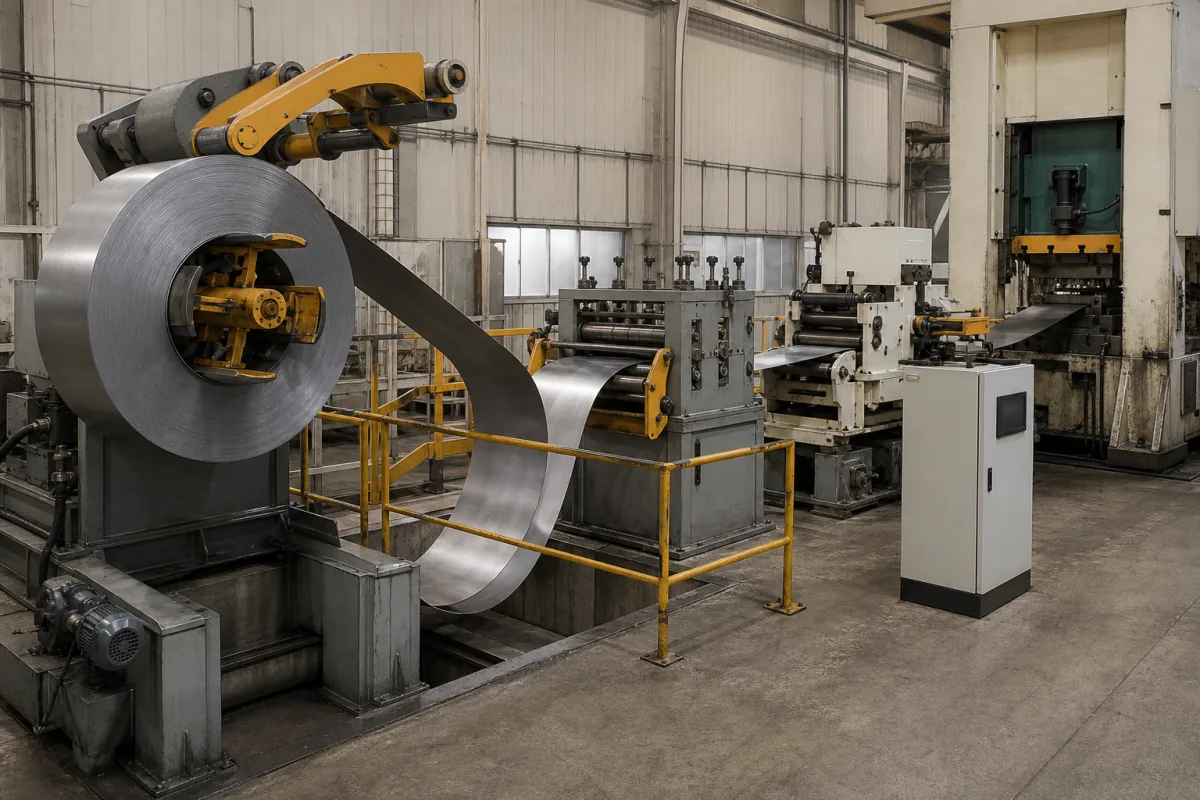
Representative product image. Confirm appearance and specifications with the manufacturer.

Product Specifications

Technical details and manufacturing context for Coil Feeding System

Definition
The coil feeding system is a critical component of a high-speed progressive stamping press, responsible for the continuous and precise supply of metal coil stock. It ensures the material is properly uncoiled, leveled to remove curvature, and advanced into the press's die station with exact timing and positioning, enabling the automated, high-volume production of stamped metal parts. The system typically comprises a decoiler that holds and pays out the metal coil, a straightener (or leveler) that removes coil set and crossbow, and a servo-driven feeder that grips the material and advances it a predetermined length (feed length) into the press. The feeder's motion is synchronized with the press cycle via a controller to ensure material is stationary and correctly positioned during the stamping operation. This product is designed for use in the fabricated metal product manufacturing industry, specifically for progressive stamping applications. It handles high-strength steel, alloy steel, and hardened tool steel, with material thickness ranging from 0.3 to 3.0 mm and width from 100 to 800 mm. Feeding speed ranges from 15 to 60 m/min, with feeding accuracy of ±0.05 mm. Coil weight capacity is 3000 to 10000 kg, and coil inner diameter is 450 to 530 mm. Feeding pitch is programmable from 0 to 9999.99 mm in increments of 0.01 mm. Motor power is 2.2 to 7.5 kW, supply voltage is 380 V AC ±10% (three-phase, 50 Hz), and operating temperature is -5 to 45°C. The enclosure rating is IP54 per IEC 60529. Machine weight ranges from 1500 to 5000 kg, and footprint (L×W×H) varies from 2500×1500×1800 to 4000×2000×2200 mm. These values are reference ranges; verify model-specific specifications with the legal manufacturer or supplier.
Working Principle
The system operates by first mounting a coil on the decoiler, which pays out the strip. The strip then passes through a straightener that removes coil set and crossbow, ensuring flatness. A servo-driven feeder grips the material and advances it a precise feed length into the press. The feeder's motion is synchronized with the press cycle via a controller, so the material is stationary and correctly positioned during stamping. This coordination ensures accurate feeding and high-speed production.
Common Materials
High-strength steel, Alloy steel, Hardened tool steel
Technical Parameters
ParameterTypical rangeNotes & selection driver
Feeding Speed15–60 m/minHigher speeds require more powerful servo drives
Feeding Accuracy±0.05 mmCritical for high-precision stamping
Material Thickness0.3–3.0 mmThicker materials require heavier straightening rollers
Material Width100–800 mmWider strips increase the required frame rigidity
Coil Weight Capacity3000–10000 kgHeavier coils require larger mandrel expansion
Coil Inner Diameter450–530 mmStandard ID range for most stamping coils
Feeding Pitch0–9999.99 mmProgrammable in increments of 0.01 mm
Motor Power2.2–7.5 kWDepends on material width and speed
Supply Voltage380 ±10% V ACThree-phase, 50 Hz
Operating Temperature-5–45 °CBelow -5°C lubricants may thicken
Enclosure RatingIP54Protects against dust and splashing waterIEC 60529
Machine Weight1500–5000 kgHeavier machines provide better stability
Footprint (L×W×H)2500×1500×1800–4000×2000×2200 mmVaries with coil capacity and straightener size

Ranges are indicative industry figures for RFQ preparation, not a supplier commitment. Confirm every value and standard with the legal manufacturer before ordering.

Components / BOM
  • Decoiler / Uncoiler
    Holds the metal coil and pays out the strip material under controlled tension.
    Material: Steel
  • Straightener / Leveler
    Removes the inherent curvature (coil set) and crossbow from the metal strip through a series of rollers.
    Material: Hardened steel
  • Servo Feeder
    The precision drive unit that grips the material and advances it the exact feed length into the press, synchronized with the press cycle.
    Material: Alloy steel
  • Feed Rollers / Grippers Part
    Contact components that apply pressure to grip the material without marring, enabling the feeder to advance it.
    Material: Hardened tool steel or polyurethane
  • Loop Control / Dancer
    Maintains a buffer loop of material between the decoiler and feeder to manage speed differences and ensure constant tension.
    Material: Steel, sensors
  • Feed Controller
    Times the feed stroke to the press cycle so the strip is stationary at the moment of stamping.

Industrial Ecosystem & Supply Chain Structure

Complementary Systems
Downstream Applications
Specialized Tooling

Application Fit & Sizing Matrix

Operational Limits
pressure: N/A (mechanical system, not pressure-based)
other spec: Strip thickness: 0.1-6.0 mm, Strip width: 50-2000 mm, Feed speed: 5-100 m/min, Coil weight: Up to 20,000 kg
temperature: Ambient to 50°C (operational environment)
Media Compatibility
✓ Cold-rolled steel strip ✓ Aluminum alloy strip ✓ Copper/brass strip
Unsuitable: Corrosive chemical processing environments (acid/alkaline exposure)
Sizing Data Required
  • Material thickness and width
  • Required feed speed and accuracy
  • Coil weight and diameter

Reliability & Engineering Risk Analysis

Failure Mode & Root Cause
Misalignment-induced wear
Cause: Incorrect installation, foundation settling, or thermal expansion causing misalignment between feed rollers, guides, and straighteners, leading to accelerated wear on bearings, shafts, and contacting surfaces.
Material slippage and surface damage
Cause: Insufficient or uneven gripping pressure from feed rollers, worn or contaminated roller surfaces, or improper tension control, resulting in coil slippage, surface scratching, or deformation of the fed material.
Maintenance Indicators
  • Audible grinding, scraping, or irregular knocking noises from rollers or guides during operation
  • Visible misalignment of the coil path, such as uneven material tracking, edge damage, or noticeable wobble in the feed mechanism
Engineering Tips
  • Implement laser alignment checks and thermal growth compensation during installation and periodic maintenance to ensure precise alignment of all feed components.
  • Use condition-based monitoring with vibration analysis on roller bearings and tension sensors to detect early wear or pressure deviations before failure occurs.

Indicative industry ranges for design and RFQ preparation. Confirm the exact figures and applicable standard with the manufacturer before specifying.

Compliance & Manufacturing Standards

Applicable Standards
CE Marking (Machinery Directive 2006/42/EC) ANSI B11.19 Performance Requirements for Safeguarding

Quoted from the published standard.

Manufacturing Precision
  • Coil Width Alignment: +/- 0.5mm
  • Feeding Speed Consistency: +/- 1% of set value
Quality Inspection
  • Dimensional Accuracy Verification (CMM)
  • Functional Safety Test (Emergency Stop, Guards)

Manufacturers of Coil Feeding System

1 company lists this product among what they make. Company figures are quoted from each company's own website; every card states where the relationship came from.

Dongguan Yiming Jia Equipment Co., Ltd.
Guangdong, CN
Listed on the company's own website · profile compiled by CNFX from public sources

Manufacturer listings support early research and capability understanding. They are not certification, ranking, or transaction guarantees.

Technical documentation
Request current drawings, revision history, and a signed specification sheet.
Manufacturing capability
Verify equipment lists, process limits, capacity, and representative production evidence.
Inspection readiness
Confirm test methods, calibrated equipment, sampling plans, and traceable reports.
Supplier transparency
Check the legal entity, factory address, ownership, certifications, and direct contacts.

CNFX does not score or rank suppliers. Buyers must verify all claims and documents with the legal manufacturer before ordering.

Supply Chain Compatible Machinery & Devices

Industrial Tube Bending Machine

An industrial tube bending machine is a CNC-controlled device designed to precisely bend metal tubes and pipes to specific angles and radii.

Explore Specs →
Precision Linear Motion Guide Rail

Precision linear guide component for smooth, accurate motion in industrial machinery

Explore Specs →
Precision Aluminum Extrusion Profile

Precision aluminum extrusion profiles are semi-finished structural components produced by forcing heated aluminum alloy through a shaped die.

Explore Specs →
Precision Hydraulic Valve Spool

A precision hydraulic valve spool is a cylindrical metal component that slides within a valve body to regulate hydraulic fluid flow, pressure, and direction.

Explore Specs →

Frequently Asked Questions

What materials can the coil feeding system handle?

The system is designed for high-strength steel, alloy steel, and hardened tool steel, with material thickness from 0.3 to 3.0 mm and width from 100 to 800 mm. Confirm compatibility with your specific material grade and dimensions.

What is the feeding accuracy of the system?

The feeding accuracy is ±0.05 mm, which is critical for high-precision stamping. Actual accuracy may depend on material condition and machine setup; verify with the manufacturer.

What are the electrical requirements?

The system requires a three-phase, 50 Hz supply voltage of 380 V AC ±10%. Motor power ranges from 2.2 to 7.5 kW. Ensure your facility meets these requirements.

What is the operating temperature range?

The recommended operating temperature is -5 to 45°C. Below -5°C, lubricants may thicken, affecting performance. For extreme environments, consult the manufacturer.

Data Basis

Editorial classification, named public sources where available, and source-reviewed manufacturer records.

Preliminary Technical Classification
This page supports structured research, RFQ preparation, and supplier evaluation. It does not replace buyer-led supplier qualification, standards review, or technical approval.
Buyer enquiry

Request manufacturing insight for Coil Feeding System

Ask for use case, specification boundaries, supplier type, and RFQ preparation information for this product.

Where it goes
Straight to the CNFX editorial desk, and to the manufacturer if this product is linked to a claimed profile. Nothing is broadcast to a supplier list.
Your details stay here
We do not sell or rent enquiry data, and we do not add you to a mailing list. Used only to answer this request.
No commission, no middleman
CNFX is a directory. We take no cut of any order and never negotiate on a supplier's behalf.
What we don't claim
A listing is not an endorsement. Qualify every supplier and verify every figure yourself before ordering.

Your business information is used only to process this request.

Thank you! Your message has been sent. We'll respond within 1–3 business days.
Sorry, we couldn't send your message. Please try again, or email us at contact@cnfx.com.

Need to Manufacture Coil Feeding System?

Compare manufacturer profiles with relevant product and process capability.

Previous Product
Welding Positioner
Last Product
Get QuotesChat