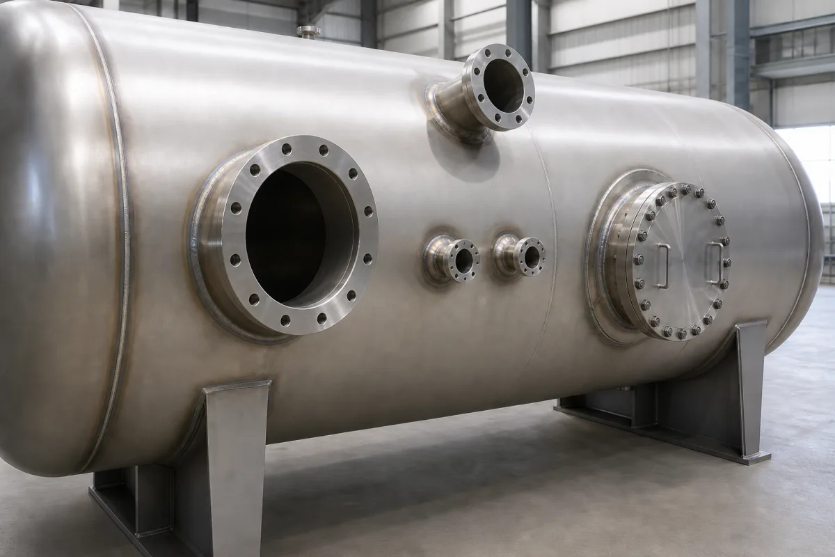
Shell nozzles for pressure vessels: long weld neck, heavy-barrel and equal-barrel forgings, reinforcing pads and tell-tale holes
Pressure vessels · Nozzle necks made from long weld neck, heavy-barrel and equal-barrel forgings, and the reinforcing pad with its vent hole
Each opening in a vessel shell is closed by a nozzle: a neck welded into the shell with a flange at its outer end for the pipe, instrument or cover. The neck can be a single forging instead of a pipe and a weld-neck flange, and the choice of forging decides how much wall the neck adds around the opening. Where the shell and neck together do not replace the metal cut away, a reinforcing pad is welded around the nozzle, and that pad brings its own detail, the vent or tell-tale hole.
Flanged nozzles on pressure vessel shells and heads built from long weld neck (LWN), heavy-barrel (HB) and equal-barrel (E) forgings or from pipe with weld-neck flanges, with their reinforcing pads and vent holes. Manway nozzles with hinged covers are covered on the Pressure vessel manway assembly page, loose flanges on the Forged steel flange page, the shell plate on the Clad low-alloy pressure vessel shell page and complete vessels on the Pressure vessel page.
CNFX editorial research · Sources checked October 17, 2026 · 5 sources
One forging, three neck walls: LWN, heavy barrel and equal barrel
Wermac describes the long welding neck flange as a standard weld neck with a considerably longer neck, used as a nozzle on a barrel or column, and the heavy-barrel and equal-barrel versions as having a different shape and thicker wall. Flange dimensions follow ASME B16.5 and B16.47, but the neck height is not standardised, so height, outside diameter and inside diameter must be stated when ordering. [3]
Texas Flange adds that these nozzles are square-cut at the end for fitting into a tank or assembly rather than bevelled to meet pipe, so they have no schedule bore; the bore of a regular LWN equals its nominal size (a 2 in LWN has a 2.00 in bore), heavy barrels excepted. It calls 9, 12 and 16 in "the more common lengths" but states there is no universal standard length, and that LWNs are forged in carbon and stainless steel, with occasional chrome-alloy and nickel-alloy requests. [1]
Give the supplier the nominal size and class, barrel type, bore, overall length, material grade, end preparation and facing.
02
What the thicker barrel buys
Editorial calculation from the table above: neck wall = (barrel OD − bore) / 2, so the 4 in Class 300 LWN has (5.75 − 4.00) / 2 = 0.875 in, the heavy barrel (6.62 − 3.83) / 2 ≈ 1.40 in, and the equal barrel (10 − 4.00) / 2 = 3.0 in. Whether that wall counts toward the opening's reinforcement is a matter for the vessel's design calculation, not the forging catalogue. [2]
Editorial calculation: reading the catalogue's base weight as applying to its 12 in length, a 16 in LWN of this size would weigh about 62 + 4 × 3.8 ≈ 77 lb, and an equal barrel about 207 + 4 × 19 = 283 lb. The per-inch reading of the column is our interpretation; confirm the weight with the supplier. [2]
03
Reinforcing pads: the tell-tale hole and what to do with it after the test
EPCLand cites ASME Section VIII Division 1 UG-37(g) as requiring reinforcing and saddle plates on nozzles to have at least one tell-tale hole, of at most NPS 1/4 in tap, to reveal leakage through the attachment weld; the hole also vents gas trapped behind the pad during welding and post-weld heat treatment, and is used for a pneumatic soap test of the pad welds. [5]
Practice after testing is not settled between the two reference sites reviewed. Wermac states that weep holes in reinforcing pads "shall be sealed upon completion of pressure test", while EPCLand says the hole must never be permanently plugged or welded shut and should, if protected at all, use a breathable sealant, plastic grease nipple or loose vent plug so a later leak stays visible. Agree the treatment in the vessel specification. [4][5]
EPCLand's sizing table, which it presents as industry practice rather than code, gives 1/8 in NPT for 2–6 in run pipe, 1/4 in NPT for 8–18 in, and two 1/4 in NPT holes 180° apart for 20–36 in. [5]
04
Nozzle schedule entries for each shell opening
Paste it into your enquiry below or into an email to a maker, then replace every bracket.
Mark: [nozzle number; service]
Size and rating: [NPS; flange class; facing]
Neck: [LWN, HB or E forging, or pipe + WN flange; bore; length]
Material: [forging grade; impact testing]
Attachment: [set-in or set-on; weld detail]
Reinforcement: [pad size and thickness; tell-tale hole and its treatment]
Loads: [external piping loads to be checked]
Explore company information and manufacturing capabilities, then discuss the scope of your project with a relevant supplier.
Share this page
Compiled and source-reviewed by the CNFX editorial team.
Each manufacturer above links to the page on that company's own website where the product is listed, with the date we checked it. How we source and review
· Page last updated 17 October 2026
Buyer questions
What is the difference between an LWN, a heavy barrel and an equal barrel?
All are long weld neck forgings; the heavy barrel has a thicker neck and the equal barrel a neck as wide as the flange. A 4 in Class 300 example runs 5.75, 6.62 and 10 in barrel OD. [3][2]
Is there a standard length for long weld neck nozzles?
No; Texas Flange names 9, 12 and 16 in as "the more common lengths" but makes them to the application. [1]
Should a reinforcing pad's tell-tale hole be plugged after the hydrotest?
Sources disagree: Wermac says seal it after the pressure test, EPCLand says never plug it permanently; settle it in the vessel specification. [4][5]
Sources and what still needs a direct check
Sources checked 2026-10-17. Texas Flange's blog and Class 300 catalogue page supply the forging types and dimensions; Wermac and EPCLand are engineering reference sites, cited for LWN ordering details and reinforcing-pad vent practice, including where they disagree.