Editorial Technical Reference

Solution Tank

This page explains how Solution Tank is classified within Machinery and Equipment Manufacturing. Technical values and manufacturer relationships are research references; confirm the current specification and supplier evidence for each order.

Technical Definition & Core Assembly

A container within a CIP cleaning system that stores and supplies cleaning or sanitizing solutions for circulation through process equipment.
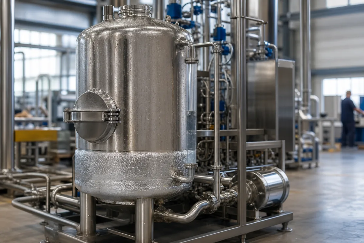
Representative product image. Confirm appearance and specifications with the manufacturer.

Product Specifications

Technical details and manufacturing context for Solution Tank

Definition
The Solution Tank is a critical component of a CIP (Clean-in-Place) Cleaning Module, designed to hold and manage the various chemical solutions (e.g., caustic, acid, sanitizer, rinse water) used in automated cleaning cycles. It typically includes features for solution level monitoring, temperature control, and connection to the CIP supply and return lines. Constructed from stainless steel (commonly 316L for corrosive chemicals), the tank is engineered to withstand specified working pressures and temperatures, with internal surface finishes suitable for hygienic cleaning. The tank's nominal capacity ranges from 500 to 10,000 liters, and its design pressure is 0.2–0.6 MPa. Design temperature spans -10 to 120 °C, accommodating hot water and caustic solutions. Wall thickness varies from 4 to 12 mm, and internal surface roughness is ≤0.8 μm Ra (ISO 4287) to facilitate sanitation. Insulation thickness of 50–100 mm helps maintain solution temperature. Empty weight ranges from 200 to 3000 kg, and overall dimensions (diameter × height) are typically 800–2500 mm × 1500–5000 mm. These values are reference ranges; actual specifications must be confirmed with the manufacturer for the specific model and application. The tank operates by receiving and storing prepared cleaning solutions. During a CIP cycle, a pump draws solution from the tank and circulates it under pressure through process piping and equipment. The solution may be heated within or before entering the tank to enhance cleaning efficacy. After use, the solution is either drained, recovered for reuse, or returned to the tank for subsequent cycles, depending on system design. When selecting a solution tank, verify that the nominal capacity matches the cleaning cycle volume and flow rate, and that the working pressure and temperature ratings align with your process requirements. Confirm material grade (e.g., 316L) for chemical compatibility, and ensure internal surface finish meets hygiene standards. Check that the tank's dimensions and weight fit your installation space and structural support. Always consult the legal manufacturer or supplier to validate model-specific values and standards.
Working Principle
The tank receives and stores a prepared cleaning solution. During a CIP cycle, a pump draws solution from the tank and circulates it under pressure through the process piping and equipment to be cleaned. The solution may be heated within or before entering the tank to enhance cleaning efficacy. After use, the solution is either drained, recovered for reuse, or returned to the tank for subsequent cycles, depending on the system design.
Common Materials
Stainless Steel 316L
Technical Parameters
ParameterTypical rangeNotes & selection driver
Nominal Capacity500–10000 LSelect based on cleaning cycle volume and flow rate
Working Pressure0.2–0.6 MPaHigher pressure may require thicker wall
Design Temperature-10–120 °CFor CIP hot water and caustic solutions
Material Grade304/316L316L for corrosive chemicalsASTM A240
Wall Thickness4–12 mmDepends on pressure and capacity
Surface Roughness (Internal)≤0.8 μm RaSmooth finish for hygienic cleaningISO 4287
Insulation Thickness50–100 mmFor temperature maintenance
Empty Weight200–3000 kgIncreases with capacity and material
Overall Dimensions (Diameter × Height)800–2500 × 1500–5000 mmVaries with capacity and design

Ranges are indicative industry figures for RFQ preparation, not a supplier commitment. Confirm every value and standard with the legal manufacturer before ordering.

Components / BOM
  • Tank Shell/Body Part
    The main pressure vessel that contains the solution.
    Material: Stainless Steel 316L
  • Level Sensor
    Monitors the volume of solution in the tank to control filling, draining, and pump operation.
    Material: Stainless Steel, PTFE
  • Manway/Cleaning Port
    Provides access for internal inspection, manual cleaning, and maintenance.
    Material: Stainless Steel
  • Insulation Jacket Part
    Minimizes heat loss from heated solutions to improve energy efficiency.
    Material: Mineral Wool, Polyurethane Foam
  • Heating Element Optional
    Brings the solution up to cleaning temperature in the tank itself.

Applied To / Applications

This component is essential for the following industrial systems and equipment:

Industrial Ecosystem & Supply Chain Structure

Complementary Systems
Downstream Applications
Specialized Tooling

Application Fit & Sizing Matrix

Operational Limits
pressure: Atmospheric to 2 bar (typical), up to 5 bar with reinforced design
flow rate: Dependent on pump capacity, typically 10-500 m³/h
temperature: -10°C to 120°C (typical), up to 150°C with special materials
slurry concentration: Up to 20% solids by weight (depending on agitation system)
Media Compatibility
✓ Caustic soda solutions (NaOH) ✓ Acid-based cleaners (nitric/phosphoric acid) ✓ Sanitizing agents (peracetic acid, hydrogen peroxide)
Unsuitable: Hydrofluoric acid or highly concentrated oxidizing agents without specialized lining
Sizing Data Required
  • Required solution volume per CIP cycle (liters)
  • Maximum flow rate needed for circulation (m³/h)
  • Available installation footprint and height constraints (meters)

Reliability & Engineering Risk Analysis

Failure Mode & Root Cause
Corrosion
Cause: Chemical attack from aggressive solution contents, leading to material degradation and potential leaks.
Structural fatigue
Cause: Cyclic loading from thermal expansion/contraction or agitation, resulting in crack initiation and propagation.
Maintenance Indicators
  • Visible leaks or weeping at welds/seams
  • Unusual noises (e.g., cracking, popping) during temperature changes or agitation
Engineering Tips
  • Implement regular internal inspections and non-destructive testing (e.g., ultrasonic thickness measurements) to monitor corrosion rates.
  • Install expansion joints or flexible connections to accommodate thermal movement and reduce stress on tank structure.

Indicative industry ranges for design and RFQ preparation. Confirm the exact figures and applicable standard with the manufacturer before specifying.

Compliance & Manufacturing Standards

Applicable Standards
ASME BPE-2022 - Bioprocessing Equipment EN 13445-3:2021 - Unfired Pressure Vessels

Quoted from the published standard.

Manufacturing Precision
  • Wall Thickness: +/-5% of nominal
  • Concentricity: 0.5mm total indicator reading
Quality Inspection
  • Hydrostatic Pressure Test
  • Surface Roughness Verification

Manufacturers of Solution Tank

Manufacturer profiles associated with Solution Tank.

Sourcing Solution Tank from China?
Tell us your specification and target quantity — we will match it against manufacturer records and come back with the factories that fit.
Request manufacturers We manufacture this

Manufacturer listings support early research and capability understanding. They are not certification, ranking, or transaction guarantees.

Technical documentation
Request current drawings, revision history, and a signed specification sheet.
Manufacturing capability
Verify equipment lists, process limits, capacity, and representative production evidence.
Inspection readiness
Confirm test methods, calibrated equipment, sampling plans, and traceable reports.
Supplier transparency
Check the legal entity, factory address, ownership, certifications, and direct contacts.

CNFX does not score or rank suppliers. Buyers must verify all claims and documents with the legal manufacturer before ordering.

Supply Chain Compatible Machinery & Devices

Heavy-Duty CNC Plasma Cutting Machine

The Heavy-Duty CNC Plasma Cutting Machine is a standalone industrial device designed for cutting conductive metals such as steel, stainless steel, aluminum, and copper alloys.

Explore Specs →
Automated Powder Coating System

Integrated industrial system for applying dry powder coatings to metal substrates.

Explore Specs →
Centrifugal Pump Impeller

The centrifugal pump impeller is a critical rotating component that converts mechanical energy from the motor into kinetic energy in fluid systems.

Explore Specs →
High-Precision CNC Laser Cutting Machine

Computer-controlled industrial machine using focused laser beams to cut sheet metal with micron-level accuracy.

Explore Specs →

Frequently Asked Questions

What is the typical capacity range for a CIP solution tank?

According to reference data, the nominal capacity ranges from 500 to 10,000 liters. The actual capacity should be selected based on the cleaning cycle volume and flow rate required for your specific process. Always confirm the exact capacity with the manufacturer for your application.

What materials are commonly used for solution tanks?

The material grade on file is Stainless Steel 316L, which is suitable for corrosive chemicals. Other grades like 304 may be available, but the reference data lists 304/316L as a range. Verify the material grade with the supplier to ensure compatibility with your cleaning solutions.

What working pressure and temperature can the tank handle?

The reference working pressure is 0.2–0.6 MPa, and the design temperature range is -10 to 120 °C. These are reference values; the actual ratings depend on the tank's design and construction. Confirm with the manufacturer for your specific model.

How do I ensure the tank meets hygiene requirements?

The internal surface roughness is specified as ≤0.8 μm Ra (ISO 4287), which is suitable for hygienic cleaning. Additionally, the tank may have insulation to maintain temperature. For specific hygiene standards, consult the manufacturer and relevant regulations for your industry.

Data Basis

Editorial classification, named public sources where available, and source-reviewed manufacturer records.

Preliminary Technical Classification
This page supports structured research, RFQ preparation, and supplier evaluation. It does not replace buyer-led supplier qualification, standards review, or technical approval.
Buyer enquiry

Request manufacturing insight for Solution Tank

Ask for use case, specification boundaries, supplier type, and RFQ preparation information for this product.

Where it goes
Straight to the CNFX editorial desk, and to the manufacturer if this product is linked to a claimed profile. Nothing is broadcast to a supplier list.
Your details stay here
We do not sell or rent enquiry data, and we do not add you to a mailing list. Used only to answer this request.
No commission, no middleman
CNFX is a directory. We take no cut of any order and never negotiate on a supplier's behalf.
What we don't claim
A listing is not an endorsement. Qualify every supplier and verify every figure yourself before ordering.

Your business information is used only to process this request.

Thank you! Your message has been sent. We'll respond within 1–3 business days.
Sorry, we couldn't send your message. Please try again, or email us at contact@cnfx.com.

Need to Manufacture Solution Tank?

Compare manufacturer profiles with relevant product and process capability.

Previous Product
Z-axis Ram/Spindle
Last Product
Get QuotesChat