Editorial Technical Reference

Spider Assembly

This page explains how Spider Assembly is classified within Machinery and Equipment Manufacturing. Technical values and manufacturer relationships are research references; confirm the current specification and supplier evidence for each order.

Technical Definition & Core Assembly

A structural component within a control rod assembly that provides radial support and positioning for control rod fingers or blades.
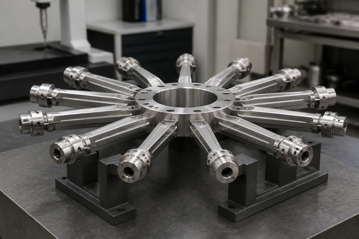
Representative product image. Confirm appearance and specifications with the manufacturer.

Product Specifications

Technical details and manufacturing context for Spider Assembly

Definition
The spider assembly is a critical structural element in nuclear reactor control rod assemblies, typically consisting of a central hub with multiple radial arms or spokes. It serves to maintain precise spacing and alignment of control rod fingers or blades, ensuring uniform neutron absorption and reliable insertion/withdrawal operations within the reactor core. This component is classified as a part-level component within the machinery and equipment manufacturing industry, specifically designed for use in control rod systems. The spider assembly functions as a rigid framework that distributes mechanical loads from control rod fingers while maintaining their geometric arrangement. During reactor operation, it withstands thermal expansion, vibration, and hydraulic forces while preserving the control rods' positioning accuracy for neutron flux regulation. Materials commonly specified for this component include Stainless Steel 316, Inconel 718, and Zirconium Alloy, each selected based on the operational environment and mechanical requirements. Key parameters include material grade (e.g., 304/316 per ASTM A240), outer diameter (100–200 mm), inner diameter (80–160 mm), height (50–120 mm), radial runout (≤0.05 mm per ISO 1101), surface roughness (Ra 0.8–1.6 μm per ISO 1302), operating temperature range (-40–350°C), tensile strength (515–620 MPa per ASTM A240), hardness (HB 150–220 per ASTM E10), weight (2–8 kg), and corrosion resistance (pass 500 hours salt spray per ASTM B117). These values are reference ranges and must be verified for the specific model and application. The spider assembly is a critical component for ensuring the safe and efficient operation of nuclear reactors, and its design and manufacturing must adhere to stringent quality standards. Buyers and engineers should consult the legal manufacturer or supplier to confirm model-specific values and standards, as the directory does not certify compliance. The component's performance directly impacts reactor control and safety, making it essential to select materials and dimensions that meet the exact requirements of the control rod assembly. Proper maintenance and inspection are necessary to detect wear, corrosion, or dimensional deviations that could affect functionality. The spider assembly is not a standalone product but an integral part of a larger system, and its failure could lead to operational issues. Therefore, it is crucial to follow the manufacturer's guidelines for installation, operation, and maintenance. The directory provides this information for reference only and does not imply any endorsement or certification.
Working Principle
The spider assembly operates as a rigid framework that distributes mechanical loads from control rod fingers while maintaining their geometric arrangement. It ensures precise spacing and alignment, allowing uniform neutron absorption and reliable insertion/withdrawal. During reactor operation, it withstands thermal expansion, vibration, and hydraulic forces, preserving positioning accuracy for neutron flux regulation. The design must accommodate material properties and dimensional tolerances to function effectively under extreme conditions.
Common Materials
Stainless Steel 316, Inconel 718, Zirconium Alloy
Technical Parameters
ParameterTypical rangeNotes & selection driver
Material Grade304/316316 for corrosive environmentsASTM A240
Outer Diameter100–200 mmMatches control rod guide tube
Inner Diameter80–160 mmClearance for rod fingers
Height50–120 mmStack-up tolerance critical
Radial Runout≤0.05 mmEnsures uniform gapISO 1101
Surface RoughnessRa 0.8–1.6 μmLower for wear resistanceISO 1302
Operating Temperature-40–350 °CAbove 350°C creep risk
Tensile Strength515–620 MPaMinimum for structural integrityASTM A240
HardnessHB 150–220Balance wear and machinabilityASTM E10
Weight2–8 kgAffects handling and inertia
Corrosion ResistancePass 500 hSalt spray test per ASTM B117ASTM B117

Ranges are indicative industry figures for RFQ preparation, not a supplier commitment. Confirm every value and standard with the legal manufacturer before ordering.

Components / BOM
  • Central Hub
    Provides the main structural connection point and distributes loads to radial arms
    Material: Stainless Steel 316
  • Radial Arms Part
    Extend outward from hub to support and position control rod fingers
    Material: Stainless Steel 316
  • Attachment Points Part
    Interface locations where control rod fingers connect to the spider arms
    Material: Inconel 718

Applied To / Applications

This component is essential for the following industrial systems and equipment:

Industrial Ecosystem & Supply Chain Structure

Complementary Systems
Downstream Applications
Specialized Tooling

Application Fit & Sizing Matrix

Operational Limits
pressure: Up to 2000 psi
other spec: Radial load capacity: 500-5000 lbf depending on configuration
temperature: -50°C to 400°C
Media Compatibility
✓ Pressurized water reactor coolant ✓ High-temperature steam ✓ Inert gas environments
Unsuitable: Corrosive chemical slurries with abrasive particulates
Sizing Data Required
  • Control rod diameter and number of fingers
  • Required radial clearance tolerance
  • Maximum expected seismic/vibration loads

Reliability & Engineering Risk Analysis

Failure Mode & Root Cause
Fatigue cracking
Cause: Cyclic loading from operational vibrations and torque transmission leading to stress concentration at weld joints or material transitions
Bearing seizure
Cause: Lubrication breakdown due to contamination, thermal degradation, or insufficient lubrication intervals causing metal-to-metal contact and overheating
Maintenance Indicators
  • Unusual rhythmic knocking or grinding noises during rotation
  • Visible cracks or deformation at weld points or spider arm connections
Engineering Tips
  • Implement vibration analysis monitoring to detect early imbalance and misalignment before fatigue damage occurs
  • Establish precision lubrication program with contamination control and scheduled oil analysis to prevent bearing degradation

Indicative industry ranges for design and RFQ preparation. Confirm the exact figures and applicable standard with the manufacturer before specifying.

Compliance & Manufacturing Standards

Applicable Standards
ISO 286-1:2010 (Geometrical product specifications - Limits and fits) ASTM A370-24 (Standard Test Methods and Definitions for Mechanical Testing of Steel Products)

Quoted from the published standard.

Manufacturing Precision
  • Bore diameter: +/-0.01mm
  • Surface flatness: 0.05mm across mating surfaces
Quality Inspection
  • Coordinate Measuring Machine (CMM) dimensional verification
  • Magnetic Particle Inspection (MPI) for surface cracks

Manufacturers of Spider Assembly

Manufacturer profiles associated with Spider Assembly.

Sourcing Spider Assembly from China?
Tell us your specification and target quantity — we will match it against manufacturer records and come back with the factories that fit.
Request manufacturers We manufacture this

Manufacturer listings support early research and capability understanding. They are not certification, ranking, or transaction guarantees.

Technical documentation
Request current drawings, revision history, and a signed specification sheet.
Manufacturing capability
Verify equipment lists, process limits, capacity, and representative production evidence.
Inspection readiness
Confirm test methods, calibrated equipment, sampling plans, and traceable reports.
Supplier transparency
Check the legal entity, factory address, ownership, certifications, and direct contacts.

CNFX does not score or rank suppliers. Buyers must verify all claims and documents with the legal manufacturer before ordering.

Supply Chain Compatible Machinery & Devices

Hydraulic Press

Industrial machine using hydraulic pressure to compress, form, or assemble materials

Explore Specs →
Heavy-Duty CNC Plasma Cutting Machine

The Heavy-Duty CNC Plasma Cutting Machine is a standalone industrial device designed for cutting conductive metals such as steel, stainless steel, aluminum, and copper alloys.

Explore Specs →
Automated Powder Coating System

Integrated industrial system for applying dry powder coatings to metal substrates.

Explore Specs →
Centrifugal Pump Impeller

The centrifugal pump impeller is a critical rotating component that converts mechanical energy from the motor into kinetic energy in fluid systems.

Explore Specs →

Frequently Asked Questions

What materials are commonly used for spider assemblies?

Common materials include Stainless Steel 316, Inconel 718, and Zirconium Alloy, each selected based on corrosion resistance, strength, and neutron absorption properties. The specific grade must be confirmed for the application.

What are the typical dimensional ranges for a spider assembly?

Typical ranges include outer diameter 100–200 mm, inner diameter 80–160 mm, and height 50–120 mm. These are reference values and must be verified for the specific model.

What standards apply to spider assembly manufacturing?

Relevant standards include ASTM A240 for material grade, ISO 1101 for radial runout, ISO 1302 for surface roughness, ASTM E10 for hardness, and ASTM B117 for corrosion resistance. Compliance must be confirmed with the supplier.

How does the spider assembly affect reactor operation?

It maintains precise spacing and alignment of control rod fingers, ensuring uniform neutron absorption and reliable insertion/withdrawal. Its structural integrity is critical for safe reactor control.

Data Basis

Editorial classification, named public sources where available, and source-reviewed manufacturer records.

Preliminary Technical Classification
This page supports structured research, RFQ preparation, and supplier evaluation. It does not replace buyer-led supplier qualification, standards review, or technical approval.
Buyer enquiry

Request manufacturing insight for Spider Assembly

Ask for use case, specification boundaries, supplier type, and RFQ preparation information for this product.

Where it goes
Straight to the CNFX editorial desk, and to the manufacturer if this product is linked to a claimed profile. Nothing is broadcast to a supplier list.
Your details stay here
We do not sell or rent enquiry data, and we do not add you to a mailing list. Used only to answer this request.
No commission, no middleman
CNFX is a directory. We take no cut of any order and never negotiate on a supplier's behalf.
What we don't claim
A listing is not an endorsement. Qualify every supplier and verify every figure yourself before ordering.

Your business information is used only to process this request.

Thank you! Your message has been sent. We'll respond within 1–3 business days.
Sorry, we couldn't send your message. Please try again, or email us at contact@cnfx.com.

Need to Manufacture Spider Assembly?

Compare manufacturer profiles with relevant product and process capability.

Previous Product
Speed Control Unit
Next Product
Spindle Assembly
Get QuotesChat