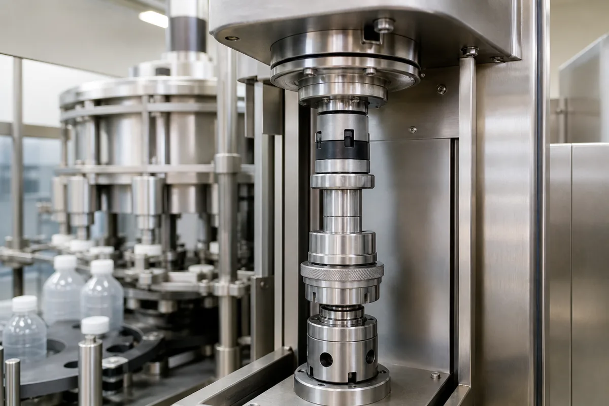
Capping spindle: the rotating head spindle with magnetic torque clutch and spring-loaded chuck on a screw capper
The spindle of a screw-capping head · magnetic torque clutch and its air gap, top-load spring and telescoping chuck, tool-less torque collars, wash-down coatings
On a rotary screw capper each head is a vertical spindle driven from the turret, ending in a chuck that grips the cap. Two things happen in that spindle: a torque-limiting clutch lets the chuck slip once the cap reaches its set tightness, and a spring lets the chuck telescope so that it presses the cap down with a controlled top load. Specifying the spindle means fixing the torque range and how it is adjusted, the top-load spring, and how the head is cleaned.
Capping head spindles for screw-capping machines: the driven spindle, magnetic or hysteresis torque clutch, top-load spring and telescoping chuck carrier, torque adjustment and quick-change chuck interface. Complete rotary and inline screw cappers, their output and application torque, are covered on the High-speed rotary bottle capping machine page, and crown, ROPP and cork closing on the Automated bottle capping machine page. Machine-tool spindles, cap chutes and closures are outside this page.
CNFX editorial research · Sources checked October 12, 2026 · 3 sources
How the magnet gap or ring offset sets the slip torque on the spindle
In a magnetic capping clutch, torque passes between two rings of magnets, one driven by the spindle and one carrying the chuck; moving the rings apart, or out of line, lowers the torque at which the chuck slips.
Alcoa's US 5,490,369 places the driving magnets (twelve in the example) in a piston-type torque ring that slides inside the housing above a magnet ring on the chuck quill. It states that varying the gap between the rings from 0.34 mm to 9 mm changes the torque limit from 30 to 3 inch-pounds, and sets the ring height with pins running in a spiral slot whose positions can be calibrated and marked on the housing. [1]
Anderson Martin's US 5,313,765 uses concentric magnet rings and shifts one ring axially by moving spacer rings from above to below it; misaligning the rings steps the torque down to approximately half the maximum of the aligned position, and with two tiers of magnets the neutral and maximum-torque positions are one magnet position, or 22½°, apart. [2] KHS's US 6,941,724 B2 nests an inner magnet ring on the spindle inside a fixed outer ring of samarium-cobalt magnets (about 2.125 in inside diameter), moves the inner ring axially with a torque-adjusting collar and detent instead of spacers, and claims a substantially linear torque-to-displacement relationship over approximately 5 to 35 in·lb. [3]
Editorial calculation: at 0.113 N·m per in·lb, Alcoa's 30–3 in·lb is about 3.4–0.34 N·m, and KHS's 5–35 in·lb about 0.56–3.95 N·m. Compare this range with the application torque the closure supplier gives, remembering that removal torque after storage is a separate figure.
Give the head builder the closure type and diameter, the application torque and tolerance, the container and its neck finish, the line speed and number of heads, and how often torque will be changed between products.
02
Top-load spring, telescoping chuck carrier and cap ejection
The spindle must also push the cap onto the neck while it turns; that force comes from a spring compressed as the chuck rides up on the cap.
In the Anderson Martin head the chuck unit slides in a sleeve and is pushed down by a coil spring whose constant may be from sixty to eighty pounds per inch; the patent says the value is not critical and that the force is changed by fitting a different spring. Guide rails stop the chuck rotating relative to the sleeve, and an elastomer O-ring in the cap receiver holds the cap while the head descends. [2] Alcoa describes the same top load arising from slight telescoping of spindle and housing against a compression spring, with the housing driven from the drive shaft through pins that can slide in their recesses as the spring compresses. [1]
Editorial calculation: 60–80 lb/in is about 10.5–14.0 N/mm, so each millimetre the chuck telescopes adds roughly 10.5 to 14 N of top load; ask the supplier for the spring rate and the compression at the capping height of your bottle.
KHS runs a knock-out rod vertically through the head to expel unneeded or jammed closures, lets its torque carrier telescope axially on the spindle, and coats the housings with a chrome-based layer about 0.0001–0.0003 in thick and about 78 Rc so that the whole head can be washed with a high-pressure water jet; its magnets are sealed in epoxy against corrosion. [3]
03
Three patented spindle heads side by side
Feature
Alcoa US 5,490,369
Anderson Martin US 5,313,765
KHS US 6,941,724 B2
Torque adjustment
Axial gap of piston torque ring; spiral slot with pins [1]
Explore company information and manufacturing capabilities, then discuss the scope of your project with a relevant supplier.
Share this page
Compiled and source-reviewed by the CNFX editorial team.
Each manufacturer above links to the page on that company's own website where the product is listed, with the date we checked it. How we source and review
· Page last updated 13 October 2026
Buyer questions
How does a magnetic capping head limit torque?
Torque passes between magnet rings on the spindle and chuck; when the cap's resistance exceeds the magnetic coupling the chuck slips. Alcoa's patent varies the ring gap from 0.34 to 9 mm for 30 to 3 in·lb. [1]
What torque range does a magnetic capping spindle cover?
KHS claims approximately 5 to 35 in·lb (about 0.56–3.95 N·m) with a substantially linear adjustment by axial ring position. [3]
Where does the top load on the cap come from?
From a spring compressed as the chuck telescopes; Anderson Martin's patent gives a spring constant of sixty to eighty pounds per inch. [2]
Sources and what still needs a direct check
Sources checked 2026-10-12. Three patents, from Alcoa, Anderson Martin Machine and KHS, describe spindle heads with magnetic torque clutches; figures are those stated in each patent's example.