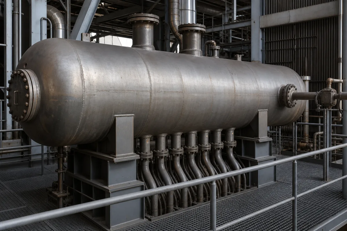
Boiler pressure parts · Steam separation internals and blowdown, drum level and swell, shell material, PWHT and hydrostatic test
A steam drum is the horizontal pressure vessel at the top of a water-tube or waste heat boiler circuit: the steam-water mixture from the risers enters it, internals separate dry steam for the outlet, and the separated water returns to the heating surfaces through the downcomers. Ask three things first: what internals the drum carries and what steam purity they are designed for, how water level will be measured and controlled under load changes, and which shell material, code, heat treatment and tests the drum is built to.
Steam drums (upper drums) for natural-circulation water-tube boilers, HRSGs and waste heat boilers, new or replacement, with their internals and nozzles. Complete boilers, lower mud drums, fire-tube boiler shells, flash tanks and separate level instruments are outside this page.
CNFX editorial research · Sources checked October 11, 2026 · 5 sources
A US Navy engineering training sheet on D-type boilers describes the steam drum internals in sequence: an internal feed pipe with side perforations distributes feedwater along the drum; baffle or apron plates separate incoming feedwater from generated steam and direct the mixture to the primary cyclone separators, which throw water out by centrifugal force; secondary chevron dryers remove additional moisture by changing the direction of steam flow; and a dry box collects the steam at the top of the drum for the outlet. The saturated steam leaving that drum is designed to be 99.75% moisture free. [1]
ORL, a drum fabricator, says it matches internal devices to the boiler's operating pressure, load range and required steam purity, with less than 0.5% moisture by mass for power plant applications on its page. [4] Editorial calculation: 99.75% moisture free means 0.25% moisture, half of a 0.5% figure; ask the supplier for the moisture or carryover figure their internals are guaranteed to, and at which load.
The US DOE's steam tip sheet on blowdown explains that dissolved solids left behind as water evaporates in the drum promote foaming and carryover of boiler water into the steam, and suspended solids form sludge. Surface or skimming blowdown removes dissolved solids concentrating near the water surface; bottom blowdown removes settled sludge. DOE gives blowdown rates of 4% to 8% of boiler feedwater flow rate (typ.), and up to 10% with high-solids make-up water. [3] The Navy sheet shows a surface blow pipe inside the steam drum for this purpose. [1]
Editorial calculation: DOE defines cycles of concentration as boiler-water impurities divided by make-up water impurities. [3] If all feedwater were make-up and solids left only with blowdown, a 4% blowdown rate would correspond to about 25 cycles and 8% to about 12.5; condensate return changes this, so give the supplier your actual make-up fraction and water analysis.
Give the supplier the boiler type and circulation, steam capacity, design and operating pressure and temperature, required steam purity, feedwater and make-up water quality, nozzle list (risers, downcomers, feedwater, steam outlet, safety valves, level, blowdown, chemical feed, vents and drains), shell inside diameter and length if fixed, design code, and whether the drum is new or replaces an existing one.
02
Plan level measurement and control for swell and shrink
ABB's application guide on drum level control explains that a level too high floods the steam purification equipment and carries water and impurities into the steam, while a level too low can cause tube failure from overheating. Steam bubbles below the surface misrepresent true level: when load rises, drum pressure drops and bubbles expand, making the level read higher than it is (swell); a level decrease from rising drum pressure is shrink. [2]
ABB's application chart rates single-element control (level only) for moderate, slow load changes such as heating plants, two-element (adding steam flow) for moderate rates, and three-element (adding feedwater flow) for wide, fast load changes. Its schemes measure level with a differential pressure transmitter whose reference leg is kept full by a constant head reservoir. [2]
The Navy sheet describes a direct-reading gauge glass on the steam drum plus remote water level indicators, of which at least two must be installed and working, with the sheet's example high and low alarm settings at 7 inches above and 6 inches below normal. Safety valves sit on the steam drum and superheater outlet, and air vents on top of the drum. [1] Editorial calculation: 7 in is about 178 mm and 6 in about 152 mm; those are alarm points for that design, not a control band, so agree level connections and alarm settings with the boiler designer.
03
Fix shell material, heat treatment and tests
ORL lists carbon steel SA-516 Gr.60/Gr.70 or Q345R for medium-pressure drums up to about 10 MPa, low-alloy SA-299, 13MnNiMoR or 15MnNiDR for thick-wall drums in the 10–19 MPa subcritical range, and Cr-Mo SA-387 Gr.11/Gr.22 for elevated-temperature HRSG and waste heat service, where it states PWHT is mandatory. It names ASME Section I, GB/T 16507 and EN 12952 as the codes it works to. [4]
ORL's reading of ASME Section I is that PWHT is mandatory for carbon steel drums thicker than 38 mm (1½ in) or for Cr-Mo materials regardless of thickness. Its process ends with RT, UT and MT of welds and a hydrostatic test at 1.5× MAWP, and its documentation package lists 3.1 mill certificates, WPS/PQR and welder records, PWHT charts, NDE records, the hydro test report and an as-built drawing. [4] Editorial calculation: for the 9.8 MPa drum in ORL's project list, 1.5× gives a 14.7 MPa test pressure; the governing code sets the actual test.
Jinan Yuanda lists Q245R, SA516 Gr.70, 12Cr1MoVg, 15CrMoVg, 19Mng and 22Mng among its drum materials. [5] Editorial note: material choice follows design pressure, temperature and code, so ask for the design calculation that sets shell thickness and corrosion allowance rather than a grade alone.
04
What to ask a drum maker about codes, internals and records
Listings are boiler pressure-part makers supplying drums for power, industrial, HRSG and waste heat boilers; ask each for the codes it is licensed to, its internals design and its documentation package.
05
Shell, manhole, nozzles, internals and level connections
Tie the internal separators row to a purity figure: ORL matches its internals to the required steam purity, and the Navy design above aims for 99.75% moisture-free steam. [4][1]
Drum fabricators for HRSG, utility and waste heat boilers
ORL lists custom and replacement drums with internals, Jinan Yuanda drums for HRSG, waste heat, industrial and utility boilers, and Dehai steam drums among its boiler pressure parts.
Suzhou Orl Power Engineering Co., Ltd.
Manufacturing site to be confirmed for the order
Lists custom and replacement steam drums with internals for power, industrial, HRSG and waste heat boilers.
Explore company information and manufacturing capabilities, then discuss the scope of your project with a relevant supplier.
Share this page
Compiled and source-reviewed by the CNFX editorial team.
Each manufacturer above links to the page on that company's own website where the product is listed, with the date we checked it. How we source and review
· Page last updated 13 October 2026
Buyer questions
What does a steam drum do?
It receives the steam-water mixture from the risers, separates steam through internals such as cyclone separators and chevron dryers, and returns water to the downcomers; one Navy boiler design aims for 99.75% moisture-free steam. [1]
What are swell and shrink in a boiler drum?
Per ABB, swell is an apparent level rise when drum pressure falls and steam bubbles expand; shrink is a level decrease when drum pressure rises. Three-element control handles fast load changes. [2]
How much blowdown does a boiler need?
DOE gives blowdown rates of 4% to 8% of boiler feedwater flow rate (typ.), and up to 10% with high-solids make-up water. [3]
What pressure is a steam drum hydro-tested at?
ORL states it hydro-tests drums at 1.5× MAWP; the governing code sets the actual test. [4]
Sources and what still needs a direct check
Sources checked 2026-10-11. ABB and ORL are companies describing their own products and practice; the US DOE and US Navy documents are government guidance. The governing boiler code sets design and test requirements.