Editorial Technical Reference

Tool Change Arm

This page explains how Tool Change Arm is classified within Machinery and Equipment Manufacturing. Technical values and manufacturer relationships are research references; confirm the current specification and supplier evidence for each order.

Technical Definition & Core Assembly

A mechanical arm that physically transfers cutting tools between the tool magazine and the machine spindle in an automatic tool-changing system.
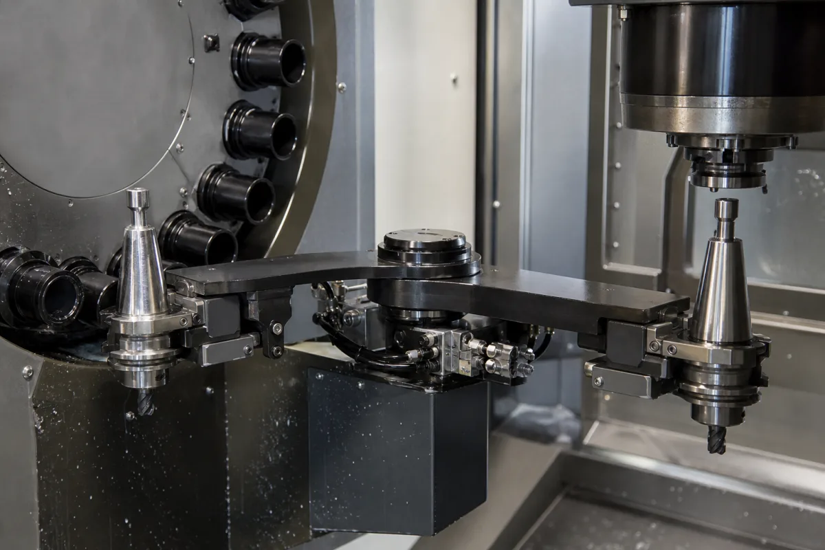
Representative product image. Confirm appearance and specifications with the manufacturer.

Product Specifications

Technical details and manufacturing context for Tool Change Arm

Definition
The Tool Change Arm is a critical component of an Automatic Tool-Changer (ATC) system, typically found on CNC machining centers, milling machines, and other automated manufacturing equipment. Its primary function is to execute the precise, automated exchange of cutting tools. It retrieves a new tool from a storage magazine (or carousel) and delivers it to the machine's spindle, while simultaneously removing the spent tool from the spindle and returning it to its designated storage location. This operation enables uninterrupted machining with multiple tools, significantly reducing non-productive time and enabling complex, multi-operation parts to be manufactured in a single setup.

Typical specifications for such arms include a load capacity of 8–15 kg, compatibility with BT40–BT50 tool tapers per ISO 7388, a swing radius of 300–600 mm, rotation speeds of 60–120 rpm, positioning accuracy of ±0.05 mm, operating pressure of 1.0–1.6 MPa, operating temperature range of -40 to 85 °C, protection class IP54–IP65 per IEC 60529, and materials such as alloy steel (e.g., 40Cr–42CrMo per GB/T 3077), cast iron, or aluminum alloy. The arm's weight typically ranges from 50–120 kg. These values are reference ranges and must be verified for the specific model and application.

When selecting a tool change arm, consider the machine's spindle taper, tool weight and dimensions, required swing radius, and cycle time. Verify that the arm's load capacity and positioning accuracy meet your machining requirements. Ensure that the operating pressure and temperature align with your facility's conditions. Confirm that the protection class suits the environment (e.g., dust or moisture). Always check the manufacturer's documentation for exact specifications and compliance with relevant standards. The arm is a component, not a standalone machine; integration with the ATC and CNC system is essential. For maintenance, monitor for wear on grippers, alignment drift, and hydraulic or pneumatic leaks. Failure to maintain proper alignment can lead to tool damage or machine downtime.
Working Principle
The arm is actuated (typically by a servo motor, pneumatic cylinder, or cam mechanism) to perform a specific, programmed motion path. A common design is the 'swing arm' or 'double gripper' type. In one cycle: 1) The arm rotates or extends to position its dual grippers—one empty, one holding the next tool—between the spindle and the tool magazine. 2) The grippers clamp onto the tool holders (e.g., CAT, BT, HSK) in both the spindle and the magazine. 3) The arm then executes a 180-degree swap motion, exchanging the positions of the two tools. 4) The arm retracts, leaving the new tool in the spindle and the used tool in the magazine. The entire sequence is controlled by the machine's CNC system in coordination with the ATC's PLC.
Common Materials
Alloy Steel, Cast Iron, Aluminum Alloy
Technical Parameters
ParameterTypical rangeNotes & selection driver
Load Capacity8–15 kgMaximum tool weight the arm can handle
Tool Taper SizeBT40–BT50Compatible with common spindle tapersISO 7388
Swing Radius300–600 mmDetermines clearance required in machine
Rotation Speed60–120 rpmFaster speeds reduce tool change time
Positioning Accuracy±0.05 mmEnsures correct tool alignment
Operating Temperature-40–85 °COutside range may affect seals and lubrication
Protection ClassIP54–IP65Higher IP for dusty or wet environmentsIEC 60529
Material40Cr–42CrMoAlloy steel for strength and wear resistanceGB/T 3077
Weight50–120 kgAffects machine dynamics and installation

Ranges are indicative industry figures for RFQ preparation, not a supplier commitment. Confirm every value and standard with the legal manufacturer before ordering.

Components / BOM
  • Arm Body Part
    The main structural frame that provides rigidity and defines the motion path of the arm.
    Material: Cast Iron or Steel
  • Gripper Mechanism
    The clamping device (often pneumatic or mechanical) that securely holds the tool holder during transfer. Typically a dual-gripper setup.
    Material: Alloy Steel
  • Drive Shaft / Actuator
    The component (e.g., servo motor, pneumatic cylinder, cam follower) that provides the rotational or linear force to move the arm.
    Material: Steel
  • Position Sensors
    Limit switches or proximity sensors that confirm the arm's 'home', 'spindle', and 'magazine' positions for precise control.
    Material: Various (Housing: Plastic/Metal)

Applied To / Applications

This component is essential for the following industrial systems and equipment:

Industrial Ecosystem & Supply Chain Structure

Complementary Systems
Downstream Applications
Specialized Tooling

Application Fit & Sizing Matrix

Operational Limits
pressure: Atmospheric operation only, no pressure rating required
other spec: Tool weight capacity: 1-25 kg, Positioning accuracy: ±0.02 mm, Cycle time: 2-8 seconds
temperature: -40°C to +85°C
Media Compatibility
✓ CNC machining centers ✓ Milling machines with ATC systems ✓ Industrial automation cells
Unsuitable: High-vibration environments (e.g., forging presses, heavy stamping)
Sizing Data Required
  • Maximum tool weight and dimensions
  • Required tool change cycle time
  • Machine spindle interface type (e.g., CAT, BT, HSK)

Reliability & Engineering Risk Analysis

Failure Mode & Root Cause
Misalignment-induced wear
Cause: Improper installation, thermal expansion, or foundation settling causing misalignment between tool change arm and spindle/tool magazine, leading to accelerated bearing and gear wear.
Hydraulic/pneumatic system failure
Cause: Contamination in hydraulic fluid or compressed air (particles, moisture), seal degradation, or pressure regulator malfunction causing erratic movement, loss of positioning accuracy, or complete arm failure.
Maintenance Indicators
  • Increased vibration or audible knocking during arm extension/retraction cycles
  • Visible fluid leaks (hydraulic oil or pneumatic air) around actuator connections or cylinders
Engineering Tips
  • Implement laser alignment checks during preventive maintenance and monitor thermal growth compensation settings to maintain precise arm-to-spindle positioning.
  • Install high-efficiency filtration in hydraulic/pneumatic supply lines and establish regular fluid analysis/contamination monitoring to prevent system degradation.

Indicative industry ranges for design and RFQ preparation. Confirm the exact figures and applicable standard with the manufacturer before specifying.

Compliance & Manufacturing Standards

Applicable Standards
ANSI B11.19 Performance Requirements for Safeguarding CE Machinery Directive 2006/42/EC

Quoted from the published standard.

Manufacturing Precision
  • Bore alignment: +/-0.01mm
  • Positioning repeatability: +/-0.005mm
Quality Inspection
  • Dimensional verification with CMM
  • Hardness testing (Rockwell C scale)

Manufacturers of Tool Change Arm

Manufacturer profiles associated with Tool Change Arm.

Sourcing Tool Change Arm from China?
Tell us your specification and target quantity — we will match it against manufacturer records and come back with the factories that fit.
Request manufacturers We manufacture this

Manufacturer listings support early research and capability understanding. They are not certification, ranking, or transaction guarantees.

Technical documentation
Request current drawings, revision history, and a signed specification sheet.
Manufacturing capability
Verify equipment lists, process limits, capacity, and representative production evidence.
Inspection readiness
Confirm test methods, calibrated equipment, sampling plans, and traceable reports.
Supplier transparency
Check the legal entity, factory address, ownership, certifications, and direct contacts.

CNFX does not score or rank suppliers. Buyers must verify all claims and documents with the legal manufacturer before ordering.

Supply Chain Compatible Machinery & Devices

Automated Powder Coating System

Integrated industrial system for applying dry powder coatings to metal substrates.

Explore Specs →
Centrifugal Pump Impeller

The centrifugal pump impeller is a critical rotating component that converts mechanical energy from the motor into kinetic energy in fluid systems.

Explore Specs →
High-Precision CNC Laser Cutting Machine

Computer-controlled industrial machine using focused laser beams to cut sheet metal with micron-level accuracy.

Explore Specs →
Industrial-Grade Hydraulic Cylinder Piston Rod

This industrial-grade piston rod is a precision-ground cylindrical component designed for use in hydraulic cylinders.

Explore Specs →

Frequently Asked Questions

What is the typical load capacity of a tool change arm?

The load capacity typically ranges from 8 to 15 kg, but this is a reference range. You must verify the exact capacity for the specific model and application with the manufacturer or supplier.

Which tool taper sizes are compatible?

The arm is compatible with BT40 to BT50 tapers per ISO 7388. However, compatibility may vary by model, so confirm with the manufacturer that your spindle and tool holders are supported.

What is the operating pressure requirement?

The operating pressure is typically 1.0 to 1.6 MPa. Ensure your facility's air or hydraulic supply meets this range, and verify the exact requirement for your specific arm.

How do I ensure proper alignment and maintenance?

Regularly check the positioning accuracy (typically ±0.05 mm) and inspect grippers for wear. Follow the manufacturer's maintenance schedule, and monitor for any deviation in tool exchange timing or unusual noises, which may indicate misalignment or wear.

Data Basis

Editorial classification, named public sources where available, and source-reviewed manufacturer records.

Preliminary Technical Classification
This page supports structured research, RFQ preparation, and supplier evaluation. It does not replace buyer-led supplier qualification, standards review, or technical approval.
Buyer enquiry

Request manufacturing insight for Tool Change Arm

Ask for use case, specification boundaries, supplier type, and RFQ preparation information for this product.

Where it goes
Straight to the CNFX editorial desk, and to the manufacturer if this product is linked to a claimed profile. Nothing is broadcast to a supplier list.
Your details stay here
We do not sell or rent enquiry data, and we do not add you to a mailing list. Used only to answer this request.
No commission, no middleman
CNFX is a directory. We take no cut of any order and never negotiate on a supplier's behalf.
What we don't claim
A listing is not an endorsement. Qualify every supplier and verify every figure yourself before ordering.

Your business information is used only to process this request.

Thank you! Your message has been sent. We'll respond within 1–3 business days.
Sorry, we couldn't send your message. Please try again, or email us at contact@cnfx.com.

Need to Manufacture Tool Change Arm?

Compare manufacturer profiles with relevant product and process capability.

Previous Product
Tool Balancer / Reel
Next Product
Tool Changer
Get QuotesChat