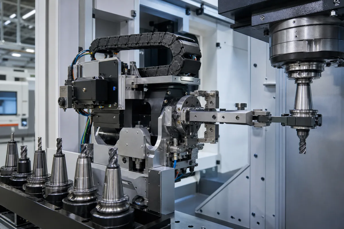
Robotic tool changers (quick-change systems) · master and tool plates, locking mechanism and fail-safe behaviour, payload, locking force and static moment capacity, repeatability, air pressure, pneumatic, electrical and signal pass-through modules, utility couplers, tool stands
A robotic tool changer couples a robot to interchangeable end-of-arm tools: a master (robot-side) plate on the robot flange locks onto a tool plate on each gripper, welding gun or other end effector, and passes air, fluids, power and signals across the joint, so one robot can pick up and set down tools in a cycle. Ask three things first: the heaviest tool and how far its centre of mass sits from the flange; how the changer stays locked if air pressure is lost; and which utilities must cross the interface.
Automatic and manual robotic tool changers for industrial and collaborative robots — master and tool plates, locking mechanisms, pneumatic, electrical, signal and fluid pass-through modules, and utility couplers that connect utilities between a robot and tools or process equipment — together with tool stands. Automatic tool changers for CNC machining centres (tool magazines and changer arms holding taper tool holders) are covered on the tool magazine page. Grippers, compliance units and cutting tools are outside this page except where compared.
CNFX editorial research · Sources checked October 11, 2026 · 5 sources
ATI's QC-11 is a pneumatically actuated changer with a suggested payload limit of 16 kg, locking force of 1100 N at 80 psi (5.5 bar), X/Y static moment capacity of 20.3 Nm and Z of 12.4 Nm, positional repeatability of 0.0102 mm, and a coupled weight of 0.245 kg (0.163 kg master side, 0.0816 kg tool side). [1] Schunk's SWK-011 robot-side unit lists the same 16 kg recommended handling weight and 1100 N locking force but Mx and My of 61 Nm and Mz of 38 Nm, with 0.015 mm repeat accuracy; Schunk notes the moments are the maximum sum of forces and moments permitted on the changer and that exceeding the handling weight shortens its life. [4]
Zimmer charts the WWR100's maximum handling weight against lever arm at accelerations of 2.5, 5 and 10 m/s² and gives maximum loads of Mr 600 Nm, My 850 Nm and Fa 16000 N, with repetition accuracy of 0.01 mm in Z and 0.02 mm in X, Y. [5] ATI's range table runs from the QC-1 (1.4 kg, 170 N, 0.983 Nm) through the QC-110 (150 kg, 12000 N, 784 Nm) to the QC-160 (300 kg, 31000 N, 2710 Nm X and Y), and ATI states its range supports payloads from 1.4 to 4000 kg. [2]
Editorial calculation: a 16 kg tool whose centre of mass sits 100 mm from the coupling face applies a static moment of about 16 × 9.81 × 0.1 ≈ 15.7 Nm, within the QC-11's 20.3 Nm X/Y rating but with little margin for acceleration; at 150 mm it reaches about 23.5 Nm, above that rating and within the SWK-011's 61 Nm. Size on moment and acceleration, not payload alone. [1][4]
Give the supplier the robot model and flange, each tool's mass and centre-of-mass offset, robot accelerations, the forces the process puts on the tool, number of tools, utilities to pass (air ports and flow, vacuum, fluids, electrical power and signals, fieldbus), available air pressure and quality, fail-safe and safety requirements, tool-presence and lock sensing, tool stand layout, environment and cycle count.
02
Plan locking safety, air supply and utility pass-through
Locking mechanisms differ. Schunk's SWS uses locking balls actuated by pistons, driven by filtered compressed air as per ISO 8573-1:2010 [7:4:4] at 4.5 to 6.9 bar, and tolerates ± 1 mm XY and ± 2° angular offset when coupling. [4] ATI's QC-11 has a patented fail-safe locking mechanism, all locking parts of Rc58 stainless steel, and No-Touch locking that allows up to 1.5 mm plate separation when locking. [1] Zimmer's WWR uses a double-acting pneumatic cylinder with an integrated spring for energy storage in case of drop in pressure and a mechanical self-locking mechanism, a 1.2 mm locking stroke, piston position sensing via a magnetic field sensor, and a robot flange to EN ISO 9409-1. [5]
Utilities cross the joint in ports and modules. The QC-11 has six M5 or #10-32 air pass-through ports and one flat for an electrical module; ATI offers over 100 pass-through modules for electrical, fluid and air transfer, plus control and valve modules that manage the lock and unlock, and modular tool stands for storing end-of-arm tooling. [1][2] The WWR100 passes air or vacuum through six integrated ports at 330 l/min per connector, with electrical and hydraulic transfer optional, and runs at 4 ... 10 bar from 5 to +80 °C. [5]
Utility couplers connect pneumatics, electrical signals, coolant or vacuum between a robot and its tools or process equipment without a full tool changer: ATI's UC-GA2 passes 10 ports of G1/4 or 3/8 NPT with a 1400 N minimum couple force, and the UC-GK1 has integrated ±3 mm X-Y compliance. [3]
Editorial calculation: Schunk's 4.5–6.9 bar operating range is 0.45–0.69 MPa, and ATI's 5.5 bar rating point is 0.55 MPa; confirm locking force at your lowest line pressure. [4][1]
03
Pneumatic and spring-locking changers, and welding-line changers with media modules
Listings range from pneumatic and spring-locking quick changers with electrical modules to changers for welding lines with media connection modules.
04
Master plate, tool plate, locking mechanism, lock sensing, utility modules and tool stand
The locking mechanism decides what happens on air loss: Schunk drives locking balls with pistons, while Zimmer's WWR adds an integrated spring and mechanical self-locking. [4][5]
Payload, moment capacity, locking force, repeatability, air pressure and weight for a tool changer order
Payload alone does not size the changer: ATI's QC-11 and Schunk's SWK-011 both list 16 kg and 1100 N, yet their X/Y static moment ratings are 20.3 Nm and 61 Nm. [1][4]
Field
What it means and published values
Ask the supplier for
Tool taper size
Robot changers mount by flange: EN ISO 9409-1 TK 100. Tapers apply to CNC tool magazines. [5]
3 companies list this product among what they make. Company figures are quoted from each
company's own website; every card states where the relationship came from.
Linghang Robot Co.,Ltd
Manufacturing site to be confirmed for the order
Lists LTC-series automatic tool changers with master and tool plates and optional servo-motor, fluid and air, and bus modules.
Explore company information and manufacturing capabilities, then discuss the scope of your project with a relevant supplier.
Share this page
Compiled and source-reviewed by the CNFX editorial team.
Each manufacturer above links to the page on that company's own website where the product is listed, with the date we checked it. How we source and review
· Page last updated 13 October 2026
Buyer questions
Is payload enough to size a tool changer?
No. ATI's QC-11 and Schunk's SWK-011 both list 16 kg and 1100 N but 20.3 Nm and 61 Nm X/Y moment ratings. [1][4]
What holds the tool if air pressure is lost?
Zimmer's WWR uses an integrated spring and a mechanical self-locking mechanism; ATI uses a patented fail-safe locking design. [5][1]
What is a utility coupler?
ATI describes it as a coupler that connects pneumatics, electrical signals, coolant or vacuum between a robot and its tools or process equipment. [3]
Sources and what still needs a direct check
Sources checked 2026-10-11. ATI, Schunk and Zimmer are tool changer makers publishing their own specifications; values for your cell must come from the supplier's datasheet and load calculation.