Editorial Technical Reference

Vapor-Liquid Separator

This page explains how Vapor-Liquid Separator is classified within Machinery and Equipment Manufacturing. Technical values and manufacturer relationships are research references; confirm the current specification and supplier evidence for each order.

Technical Definition & Core Assembly

A device that separates vapor from liquid phases in a vacuum evaporation system.
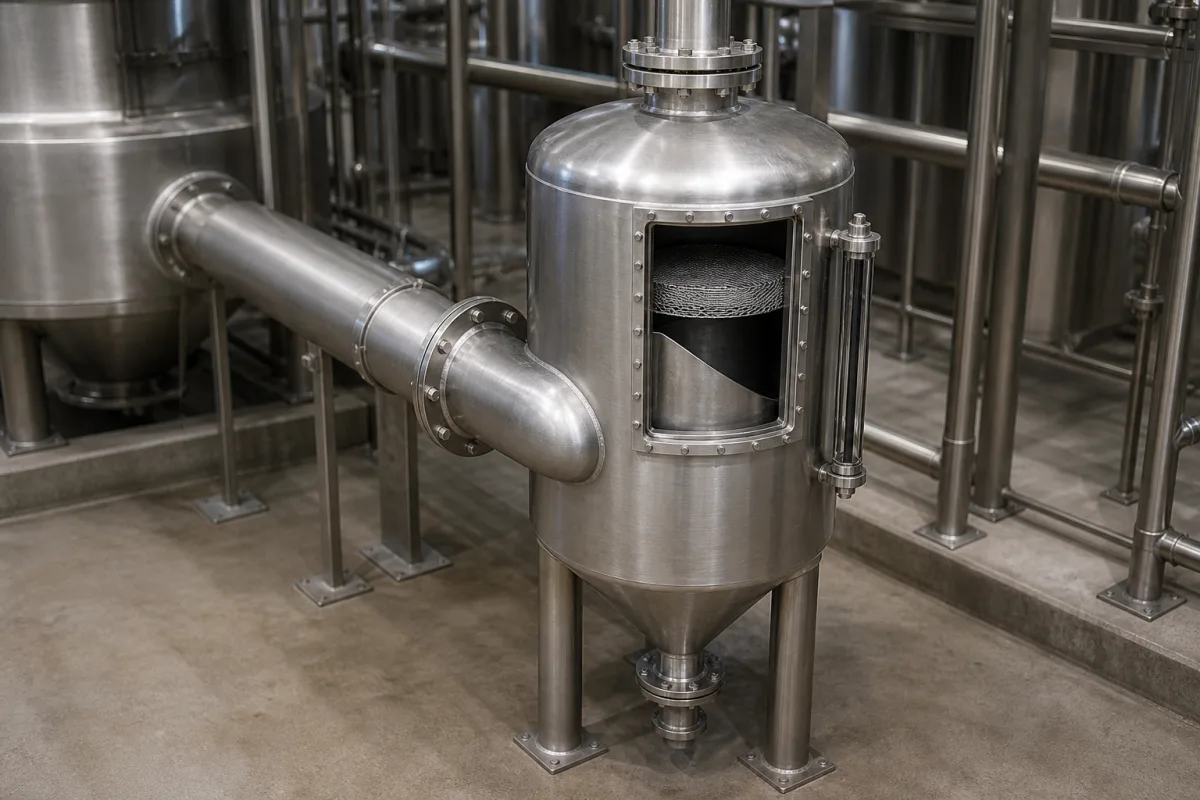
Representative product image. Confirm appearance and specifications with the manufacturer.

Product Specifications

Technical details and manufacturing context for Vapor-Liquid Separator

Definition
The Vapor-Liquid Separator is a component used in machinery and equipment manufacturing, specifically within multi-stage vacuum evaporator trains. Its primary function is to separate vaporized solvent or water from the concentrated liquid product stream, ensuring product purity and preventing liquid carryover into subsequent stages or the vacuum system. The separator operates by directing the vapor-liquid mixture into a chamber where a sudden change in velocity and direction, often aided by internal baffles or demister pads, causes denser liquid droplets to coalesce and fall out of the vapor stream by gravity, allowing purified vapor to exit separately. This device is typically constructed from stainless steel grades such as 304 or 316L, with 316L recommended for corrosive media. Key parameters include an operating pressure range of 1.0–1.6 MPa, a design temperature range of -40–150°C (per GB/T 150, with special gasket material required above 150°C), nominal diameters from DN25 to DN300 (per GB/T 1047, with larger sizes on request), separation efficiency of 99.5–99.9% for droplet sizes greater than 10 μm, pressure drop of 0.01–0.05 MPa at rated flow, flow capacity of 1–50 m³/h based on gas flow at operating conditions, and weight ranging from 15–200 kg depending on size and material. Connection types include flange or thread, with flange rating matching pressure class per HG/T 20592. Surface treatment options are sandblasted or polished, with polished finish for sanitary applications. Inlet/outlet orientation can be vertical or horizontal, with vertical preferred for space saving. Gasket materials include PTFE for high temperature and EPDM for steam. These values are reference ranges and must be verified for the specific model and application with the legal manufacturer or supplier. The separator is a critical component that requires proper selection based on process conditions, and its performance should be validated through testing or manufacturer data.
Working Principle
The vapor-liquid mixture enters the separator chamber, where a sudden increase in cross-sectional area reduces velocity. Internal baffles or demister pads cause the vapor to change direction, while denser liquid droplets, due to inertia, collide and coalesce. The enlarged droplets then fall by gravity to the bottom, where they are collected and removed. The purified vapor, now free of entrained liquid, exits from the top or side outlet. This mechanism relies on density difference and gravitational settling, with efficiency dependent on droplet size and gas velocity.
Common Materials
Stainless Steel (e.g., 304, 316L)
Technical Parameters
ParameterTypical rangeNotes & selection driver
Operating Pressure1.0–1.6 MPa
Design Temperature-40–150 °CAbove 150°C requires special gasket materialGB/T 150
Nominal DiameterDN25–DN300 mmLarger sizes on requestGB/T 1047
Separation Efficiency99.5–99.9 %For droplet size > 10 μm
Pressure Drop0.01–0.05 MPaAt rated flow
Flow Capacity1–50 m³/hBased on gas flow at operating conditions
Body Material304/316L316L for corrosive mediaASTM A240
Gasket MaterialPTFE/EPDMPTFE for high temp, EPDM for steam
Connection TypeFlange/ThreadFlange rating matches pressure classHG/T 20592
Weight15–200 kgDepends on size and material
Surface TreatmentSandblasted/PolishedPolished for sanitary applications
Inlet/Outlet OrientationVertical/HorizontalVertical preferred for space saving

Ranges are indicative industry figures for RFQ preparation, not a supplier commitment. Confirm every value and standard with the legal manufacturer before ordering.

Components / BOM
  • Inlet Nozzle Part
    Directs the vapor-liquid mixture into the separator tangentially or with a deflector to initiate separation.
    Material: Stainless Steel
  • Demister Pad / Mesh Part
    Coalesces fine liquid droplets from the vapor stream through impingement.
    Material: Stainless Steel Wire Mesh
  • Vapor Outlet Nozzle Part
    Allows the separated vapor to exit the vessel to the next stage or condenser.
    Material: Stainless Steel
  • Liquid Outlet Nozzle Part
    Drains the separated liquid from the bottom of the vessel.
    Material: Stainless Steel
  • Level Gauge / Sight Glass
    Provides visual indication or control signal for the liquid level inside the separator.
    Material: Glass / Stainless Steel Housing
  • Separator Vessel
    The vessel itself: the volume where velocity drops enough for droplets to fall out.

Applied To / Applications

This component is essential for the following industrial systems and equipment:

Industrial Ecosystem & Supply Chain Structure

Complementary Systems
Downstream Applications
Specialized Tooling

Application Fit & Sizing Matrix

Operational Limits
pressure: Vacuum to 10 bar
flow rate: Up to 50 m³/h
temperature: -20°C to 200°C
slurry concentration: Up to 30% solids by weight
Media Compatibility
✓ Water vapor and condensate ✓ Organic solvent vapors and liquids ✓ Food-grade steam and condensate
Unsuitable: Highly corrosive acidic environments (e.g., concentrated sulfuric acid)
Sizing Data Required
  • Vapor flow rate (kg/h or m³/h)
  • Liquid droplet size distribution (microns)
  • Required separation efficiency (%)

Reliability & Engineering Risk Analysis

Failure Mode & Root Cause
Corrosion-induced wall thinning
Cause: Exposure to corrosive process fluids (e.g., acids, chlorides) combined with moisture condensation, leading to material degradation and loss of structural integrity.
Liquid carryover or gas bypass
Cause: Inadequate separation efficiency due to fouling of internals (demister pads, baffles), improper liquid level control, or exceeding design flow rates, resulting in downstream equipment damage.
Maintenance Indicators
  • Visible external corrosion, pitting, or weeping at seams/welds
  • Abnormal pressure fluctuations or increased differential pressure across the separator
Engineering Tips
  • Implement regular ultrasonic thickness testing (UTT) at corrosion-prone areas and maintain a corrosion management program with appropriate material selection (e.g., corrosion-resistant alloys or linings).
  • Optimize and routinely inspect internals (demisters, baffles, level controls), ensure proper liquid drainage, and adhere to design operating envelopes for flow rates and temperatures.

Indicative industry ranges for design and RFQ preparation. Confirm the exact figures and applicable standard with the manufacturer before specifying.

Compliance & Manufacturing Standards

Applicable Standards
ISO 5167: Measurement of fluid flow by means of pressure differential devices inserted in circular cross-section conduits running full ASME B31.3: Process Piping DIN EN 13445: Unfired pressure vessels

Quoted from the published standard.

Manufacturing Precision
  • Bore diameter: +/-0.05mm
  • Surface finish: Ra 0.8μm
Quality Inspection
  • Hydrostatic pressure test
  • Dimensional verification with CMM

Manufacturers of Vapor-Liquid Separator

Manufacturer profiles associated with Vapor-Liquid Separator.

Sourcing Vapor-Liquid Separator from China?
Tell us your specification and target quantity — we will match it against manufacturer records and come back with the factories that fit.
Request manufacturers We manufacture this

Manufacturer listings support early research and capability understanding. They are not certification, ranking, or transaction guarantees.

Technical documentation
Request current drawings, revision history, and a signed specification sheet.
Manufacturing capability
Verify equipment lists, process limits, capacity, and representative production evidence.
Inspection readiness
Confirm test methods, calibrated equipment, sampling plans, and traceable reports.
Supplier transparency
Check the legal entity, factory address, ownership, certifications, and direct contacts.

CNFX does not score or rank suppliers. Buyers must verify all claims and documents with the legal manufacturer before ordering.

Supply Chain Compatible Machinery & Devices

Hydraulic Press

Industrial machine using hydraulic pressure to compress, form, or assemble materials

Explore Specs →
Heavy-Duty CNC Plasma Cutting Machine

The Heavy-Duty CNC Plasma Cutting Machine is a standalone industrial device designed for cutting conductive metals such as steel, stainless steel, aluminum, and copper alloys.

Explore Specs →
Automated Powder Coating System

Integrated industrial system for applying dry powder coatings to metal substrates.

Explore Specs →
Centrifugal Pump Impeller

The centrifugal pump impeller is a critical rotating component that converts mechanical energy from the motor into kinetic energy in fluid systems.

Explore Specs →

Frequently Asked Questions

What is the typical operating pressure range for this separator?

The reference operating pressure range is 1.0–1.6 MPa. Verify the actual requirement with the manufacturer.

Can this separator handle high-temperature applications?

The design temperature range is -40–150°C per GB/T 150. Above 150°C, special gasket material is required. Confirm the maximum temperature with the supplier for your specific process.

What materials are available for the separator body?

The body material is typically stainless steel 304 or 316L, with 316L recommended for corrosive media. The material grade should be confirmed based on the process fluid and compatibility.

How is the separation efficiency defined?

The separation efficiency is 99.5–99.9% for droplet sizes greater than 10 μm. This is a reference value; actual efficiency depends on operating conditions and should be verified with the manufacturer.

Data Basis

Editorial classification, named public sources where available, and source-reviewed manufacturer records.

Preliminary Technical Classification
This page supports structured research, RFQ preparation, and supplier evaluation. It does not replace buyer-led supplier qualification, standards review, or technical approval.
Buyer enquiry

Request manufacturing insight for Vapor-Liquid Separator

Ask for use case, specification boundaries, supplier type, and RFQ preparation information for this product.

Where it goes
Straight to the CNFX editorial desk, and to the manufacturer if this product is linked to a claimed profile. Nothing is broadcast to a supplier list.
Your details stay here
We do not sell or rent enquiry data, and we do not add you to a mailing list. Used only to answer this request.
No commission, no middleman
CNFX is a directory. We take no cut of any order and never negotiate on a supplier's behalf.
What we don't claim
A listing is not an endorsement. Qualify every supplier and verify every figure yourself before ordering.

Your business information is used only to process this request.

Thank you! Your message has been sent. We'll respond within 1–3 business days.
Sorry, we couldn't send your message. Please try again, or email us at contact@cnfx.com.

Need to Manufacture Vapor-Liquid Separator?

Compare manufacturer profiles with relevant product and process capability.

Previous Product
Vacuum System
Next Product
Variable Frequency Drive
Get QuotesChat