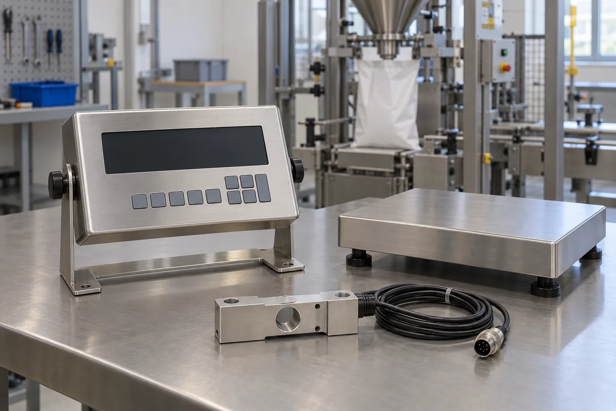
Weight indicator / controller (digital weighing indicator for load cells)
Digital weighing indicators and controllers for load-cell scales · Accuracy class and number of intervals, error limits, signal per interval, load cell excitation and count, outputs and control
A weight indicator (or weighing controller) powers the load cells of a scale, converts their millivolt signal to a weight reading and, in controller versions, switches outputs or sends data to run batching, filling or checkweighing. Ask three things first: what capacity, scale interval and accuracy class the scale must meet, whether the indicator can excite your load cells and resolve the signal they give per interval, and which outputs, setpoints and communication the process needs.
Digital weighing indicators, weighing controllers and transmitters for strain-gauge load-cell scales: platform, floor, truck, tank, hopper and batching scales. Drilling-rig hook-load (deadline) weight indicators, load cells themselves and complete scales are outside this page except where compared.
CNFX editorial research · Sources checked October 11, 2026 · 4 sources
Set accuracy class, number of intervals and error limits
OIML R 76-1 (2006), the international recommendation for non-automatic weighing instruments, defines the number of verification scale intervals as n = Max / e. For medium accuracy Class III it allows a verification interval e of 0.1 g to 2 g with 100 to 10,000 intervals, or e of 5 g or more with 500 to 10,000 intervals, and a minimum capacity of 20 e. Its maximum permissible errors on initial verification for Class III are ±0.5 e from 0 to 500 e, ±1 e above 500 e to 2,000 e and ±1.5 e above 2,000 e to 10,000 e. [1]
When an indicator is tested as a separate module, R 76-1 gives it a fraction pi of the complete instrument's error limits; the standard fraction is 0.5 and it may lie between 0.3 and 0.8, stated by the maker. The sum of the squares of the fractions of all modules (indicator, load cells, connecting elements) must not exceed 1. The recommendation also requires that the instrument not print, store data, set zero or tare while equilibrium is disturbed. [1]
Editorial calculation: a 30 t truck scale with e = 10 kg has n = 30,000 / 10 = 3,000 intervals, within Class III. Its error limits on initial verification are ±5 kg up to 5 t (500 e), ±10 kg up to 20 t (2,000 e) and ±15 kg up to 30 t; with the standard fraction 0.5, the indicator's share is ±2.5, ±5 and ±7.5 kg. [1]
Give the supplier the scale type and capacity, scale interval and accuracy class, whether the scale is used for trade (legal-for-trade approval), the number, rated output, resistance and capacity of the load cells, cable length, power supply, required setpoints and relay outputs, communication (RS232, RS485, Modbus, analogue), enclosure and ingress protection, operating temperature, and display or printer needs.
02
Match the indicator to the load cells and the process
Top Sensor Technology lists a weight control indicator with DC 12–30 V supply, signal input range 0.4–6 mV/V, excitation 5 V DC ±2% at 100 mA, 24-bit A/D conversion at 10, 40, 640 or 1,280 conversions a second, up to six 350 Ω load cells, RS485, RS232 or analogue output (0–20 mA, 4–20 mA or ±10 V), Modbus RTU or free protocol, and 96 × 71 × 48 mm dimensions. [2]
R 76-1 Annex F checks that modules are compatible: the signal per verification interval, u = C × Uexc × R × e / (Emax × N), must be at least the indicator's minimum input voltage per interval, Δumin, where C is the load cell rated output (mV/V), Uexc the excitation voltage, R the lever reduction ratio, Emax the load cell capacity and N the number of load cells; its worked examples use indicators with Δumin = 1 µV and 3,000 intervals. [1]
Editorial calculation: with four 20 t load cells of 2 mV/V (illustrative), 5 V excitation, R = 1 and e = 10 kg, u = 2 × 5 × 10 / (20,000 × 4) mV = 1.25 µV per interval, above a 1 µV Δumin. Six 350 Ω cells in parallel present about 58 Ω, drawing about 86 mA at 5 V, within the listed 100 mA. [1][2]
Transcell's TI-500 series page gives a second maker's figures: 5 V DC excitation driving up to eight 350 Ω load cells, a 24-bit sigma-delta A/D converter, a 6-digit 0.8 in LED display, RS-232, RS-485 and 4–20 mA outputs with optional Ethernet, AC power with a rechargeable internal battery, and NTEP Class III variants. It lists five variants: TI-500E (general industrial), TI-500SS (washdown stainless), TI-500RF (wireless), TI-500 plus-J (with junction box) and TI-500 plus-IS (intrinsically safe), and notes that a 2 mV/V load cell excited at 5 V produces 10 mV at full load. [4] Editorial calculation: eight 350 Ω cells in parallel present 350 / 8 ≈ 43.8 Ω, drawing about 5 / 43.8 ≈ 114 mA of excitation current, against about 86 mA for the six cells Top Sensor allows at 100 mA; and if that 10 mV full-load signal is divided into 10,000 intervals, each interval is only 1 µV, which the indicator's minimum input per interval must not exceed. [4][2][1]
03
Top Sensor Technology and GALOCE indicator listings
Only Top Sensor Technology's control indicator comes with the excitation, input-range and conversion figures used in the checks above; ask GALOCE (Xi'an) M&C Technology Co., Ltd. for the same figures before comparing. [2]
The suppliers reviewed list weighing indicators, controllers and transmitters with load cells; ask each for accuracy class and approval certificates, minimum input voltage per interval, excitation current, conversion rate, setpoints and outputs, communication protocols and enclosure rating.
04
Check zero tracking, motion, temperature and power limits (US)
For scales used in trade in the United States, NIST Handbook 44 Section 2.20 (2026 edition) sets limits that sit in the indicator's firmware and electronics. For scales manufactured on or after January 1, 2007, the automatic zero-tracking mechanism may rezero no more than 3.0 scale divisions on vehicle, axle-load and railway track scales and 0.5 scale division on all other scales; Class III L devices with zero tracking need a sealable means to disable it for inspection. Digital indicating elements with recording elements may record only when the indication is stable within ±3.0 scale divisions for vehicle, axle-load, livestock and railway track scales, and ±1.0 scale division for other scales covered by that clause. [3]
Handbook 44 also limits environmental effects. If no temperature limits are marked on a Class III, III L or IIII device, it must meet tolerances from −10 °C to 40 °C; a marked range must span at least 30 °C for these classes. Zero may drift no more than one e per 5 °C change (three e for Class III L). AC-powered devices must stay within tolerance from −15 % to +10 % of the marked nominal line voltage at 60 Hz, a power interruption must not produce out-of-tolerance values, and radio-frequency disturbance may shift the reading by no more than one e unless the indication blanks. [3]
For load cells with NTEP certificates, Handbook 44 requires the minimum load cell verification interval vmin to be no more than e / √N for scales without lever systems, where N is the number of load cells. Editorial calculation: a scale with e = 10 kg on four load cells needs vmin ≤ 10 / √4 = 5 kg per cell. Ask the indicator supplier for its NTEP certificate, accuracy class and nmax marking, and confirm the zero-tracking and motion settings match the scale type. [3]
05
Excitation, conversion, logic, display and output blocks
The excitation supply and the A/D converter are the two blocks the Annex F signal-per-interval check applies to; the others decide what the indicator shows, stores and switches. [1]
Where OIML and Top Sensor give numbers for the indicator sheet
Accuracy class and input sensitivity carry the OIML and Top Sensor figures; storage temperature, ingress protection and enclosure material have no published value here and must come from the supplier.
Top Sensor Technology lists weighing and control indicators together with load cells, transmitters and truck scales; GALOCE (Xi'an) M&C Technology Co., Ltd. lists platform, truck and belt scale indicators and weighing controllers.
Top Sensor Technology
Manufacturing site to be confirmed for the order
Lists weighing indicators and control indicators with load cells, transmitters and truck scales.
Explore company information and manufacturing capabilities, then discuss the scope of your project with a relevant supplier.
Share this page
Compiled and source-reviewed by the CNFX editorial team.
Each manufacturer above links to the page on that company's own website where the product is listed, with the date we checked it. How we source and review
· Page last updated 13 October 2026
Buyer questions
How many divisions can a Class III weight indicator have?
OIML R 76-1 allows Class III instruments 500 to 10,000 verification intervals for e of 5 g or more (100 to 10,000 for e of 0.1 g to 2 g). [1]
How do I check an indicator suits my load cells?
Calculate the signal per interval, C × Uexc × R × e / (Emax × N), and compare it with the indicator's minimum input per interval (OIML R 76-1 Annex F). [1]
How many load cells can one indicator drive?
It depends on excitation current; Top Sensor lists up to six 350 Ω cells at 5 V and 100 mA. [2]
How much automatic zero tracking may a trade-approved weight indicator apply in the US?
NIST Handbook 44 limits automatic zero tracking on scales made on or after January 1, 2007 to 3.0 scale divisions for vehicle, axle-load and railway track scales and 0.5 scale division for all other scales. [3]
How many 350 Ω load cells can a 5 V indicator excite?
Transcell lists its TI-500 series at up to eight 350 Ω cells on 5 V DC excitation, about 114 mA in total by calculation; Top Sensor lists six cells at 100 mA. [4][2]
Sources and what still needs a direct check
Sources checked 2026-10-11. OIML R 76-1 is the international recommendation for non-automatic weighing instruments; Top Sensor and Transcell describe their own indicators. National legal-metrology rules govern trade use.