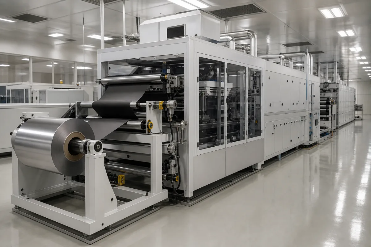
Lithium-ion electrode coating machines · Slot-die coating on foil, foil width and line speed by scale, one- or two-sided and intermittent coating, flotation dryer length, NMP recovery, and in-line coat-weight and thickness measurement
A lithium-ion battery electrode coating machine unwinds copper or aluminium current-collector foil, applies a metered layer of electrode slurry through a slot die (or comma bar) on one or both sides, continuously or in intermittent patches, and dries it in a long oven before rewinding the coated web for calendering and slitting. Ask three things first: what foil width, speed and annual capacity the line must reach, which coating mode and dryer design it uses, and how solvent is recovered and coat weight and thickness are measured on line.
Roll-to-roll coating lines for lithium-ion battery electrodes: unwind and rewind, slot-die or comma-bar coating heads, dryers and integrated solvent recovery, from R&D to mass production. Slurry mixers, calenders, slitting machines (see battery electrode slitting machine) and dry-electrode processes are outside this page except where integrated.
CNFX editorial research · Sources checked October 11, 2026 · 4 sources
Dürr MEGTEC's advanced battery electrode brochure (2019) lists six coating lines from R&D to mass production: foil widths of 250, 300, 350, 700, 1,400 and 2,200 mm; speeds of 0.5, 3, 5, 20, 40 and 60 m/min; and capacities of 0.1, 5, 50, 500, 2,000 and 5,000 MW per year. The smaller two coat one side per pass; the pilot and larger lines coat both sides simultaneously, side A by slot die on a backing roll or tensioned web and side B by slot die on a tensioned web, with multi-lane coating and intermittent coating as options and non-stop automatic unwind and rewind on the largest lines. [1]
Hallemans and co-authors (University of Oxford and partners, 2025) describe roll-to-roll electrode manufacture in which the metallic foil can run at up to 100 m/min, slurry is extruded through a slot die, dried through an extended line of ovens and calendered to 30–120 µm thickness and 30–40 vol% porosity, following a recipe that sets coater flow rate, oven temperatures and calender pressure. They note that edge effects across the coating width increase with line speed. [2]
Editorial note: specify the electrode (anode or cathode, foil type and thickness), wet and dry coat weight, coating width and lane pattern, and whether intermittent (patched) coating is needed for your cell format before comparing line sizes.
Give the supplier the electrode type and chemistry, solvent (NMP or water), foil material, width and thickness, coating width, lanes and pattern, wet and dry coat weight, coating mode (continuous or intermittent, one- or two-sided), line speed, dryer temperature limits, solvent recovery and emission limits, in-line gauges, cleanroom or dry-room class, utilities and footprint.
02
Check the dryer, solvent recovery and in-line measurement
The same brochure gives dryer types and lengths of 0.6 m and 1–3 m roll-support dryers on R&D and lab coaters and flotation dryers of 6 m, 15–30 m, 40–48 m and 50–70 m on the pilot to largest lines. It describes NMP recovery by chilled-water condensation of dryer exhaust with heat-exchanged make-up air returned to the dryer, a typical recovery rate above 99%, and on-site distillation to electronic-grade NMP. [1]
The review lists in-line measurements used or proposed for electrodes, including lasers for thickness, X-ray and beta gauges for coat weight, digital imaging and infrared and ultrasonic sensors, and names electrode thickness, coat weight, porosity and binder distribution as product properties to control through line speed, coating slot and dryer settings. [2]
Editorial calculation: at 40 m/min through a 40–48 m dryer the web spends about 60–72 s drying, and at 60 m/min through 50–70 m about 50–70 s; ask the supplier to show the drying curve and binder-migration limits for your coat weight at the quoted speed. [1]
03
Balance drying speed against binder migration
Toyota's US patent 8,962,098 (priority 22 April 2009, granted 24 February 2015) states the trade-off the dryer has to manage: electrode makers want the paste dried quickly to shorten cycle time and cut dryer running cost, but above a minimum drying speed convection (migration) in the wet coating carries the binder, lighter than the active material, up away from the foil, which weakens the peel strength between collector and coating. In its line the drying speed is set by the web speed through the furnace and the heat supplied by heated air. [3]
The patent's example line conveys the collector at 60 m/min, feeds the paste to the die manifold at room temperature (25 to 30 °C), and uses aluminium foil for the positive and copper foil for the negative electrode, with SBR binder for water-based pastes, PVDF for organic-solvent pastes and CMC as thickener. [3]
Its remedy mounts laser oscillators on the slot die beside the manifold, aimed upstream of the slit at the paste–foil interface at close to a right angle to limit reflection from the metal foil, so the binder sets at the interface first; the embodiment uses ultraviolet lasers of 405 nm (300 mW output, 200 mW continuous, 450 mW pulse), and suggests InGaAsSb semiconductor lasers at 2.85 µm, resonant with water, for aqueous pastes. The patent states this allows high-speed drying with improved peel strength and a shorter dryer. [3]
Editorial note: whatever the dryer design, ask the supplier for peel-strength results on your slurry at the quoted line speed and dryer zone temperatures, and how the zone profile is set to limit binder migration. The 60 m/min example matches the top speed of the largest line in the Dürr MEGTEC range. [3][1]
04
Find electrode coating machine manufacturers
No manufacturer record has been reviewed for this product yet. Send your specification and CNFX will match it against manufacturer records.
05
Ask for adhesion data at the drying rate you will run
Kumberg and co-authors at the Karlsruhe Institute of Technology (KIT) dried water-based graphite anodes on 10 μm copper foil in a batch impingement dryer with 20 slot nozzles (heat transfer coefficient 35 W/m²K, coating speed 6 m/min). Drying rates of 0.5, 2.2 and 5 g/m²s were set with plate and air temperatures of around 30, 50 and 65 °C; a tenfold rise in drying rate caused a massive adhesion loss in the single-layer reference electrode. [4]
A spherical-graphite bottom layer coated simultaneously under the top layer kept adhesion at high drying rates: dried at 5 g/m²s in 14 s at 1.9 mAh/cm², the two-layer anode matched at 3C the discharge capacity of the reference dried within 134 s, a tenfold acceleration. [4]
Editorial calculation: at the 60 m/min of the largest Dürr line (1 m/s) [1], 14 s of drying needs about 14 m of dryer and 134 s about 134 m. These are laboratory results; ask the supplier for drying rate, temperatures and peel strength on your slurry.
Fill the specification fields with values for your line
An electrode coating machine quotation needs values for your line. The table explains each field, gives published values where a reviewed source states them, and says what to obtain from the supplier.
Explore company information and manufacturing capabilities, then discuss the scope of your project with a relevant supplier.
Share this page
Compiled and source-reviewed by the CNFX editorial team.
Published product pages show what a company offers, not tested performance. Confirm the legal seller, factory, acceptance tests and scope for your order. How we source and review
· Page last updated 13 October 2026
Buyer questions
How fast do electrode coating lines run?
One supplier's range runs from 0.5 m/min for R&D to 60 m/min for production; a review cites foil speeds up to 100 m/min. [1][2]
How long are electrode dryers?
From under a metre on R&D coaters to 50–70 m of flotation dryer on the largest line in one range. [1]
How much NMP can be recovered?
One supplier gives a typical recovery rate above 99% using condensation and distillation. [1]
Why can't an electrode dryer simply run hotter and faster?
Toyota's US patent 8,962,098 explains that above a minimum drying speed convection moves the binder away from the foil, weakening peel strength between foil and coating. [3]
Can an electrode be dried faster without losing adhesion?
In a Karlsruhe Institute of Technology study, a simultaneously coated two-layer graphite anode dried at 5 g/m²s in 14 s and matched at 3C the discharge capacity of a reference dried within 134 s, while the single-layer reference lost adhesion at the tenfold higher drying rate. [4]
Sources and what still needs a direct check
Sources checked 2026-10-11. Dürr MEGTEC describes its own coating lines and is used here to show what a specification covers; the Oxford-led review summarises electrode manufacturing practice; the Toyota patent describes its own drying problem and remedy. Performance for your line must come from the supplier's acceptance tests on your slurry.