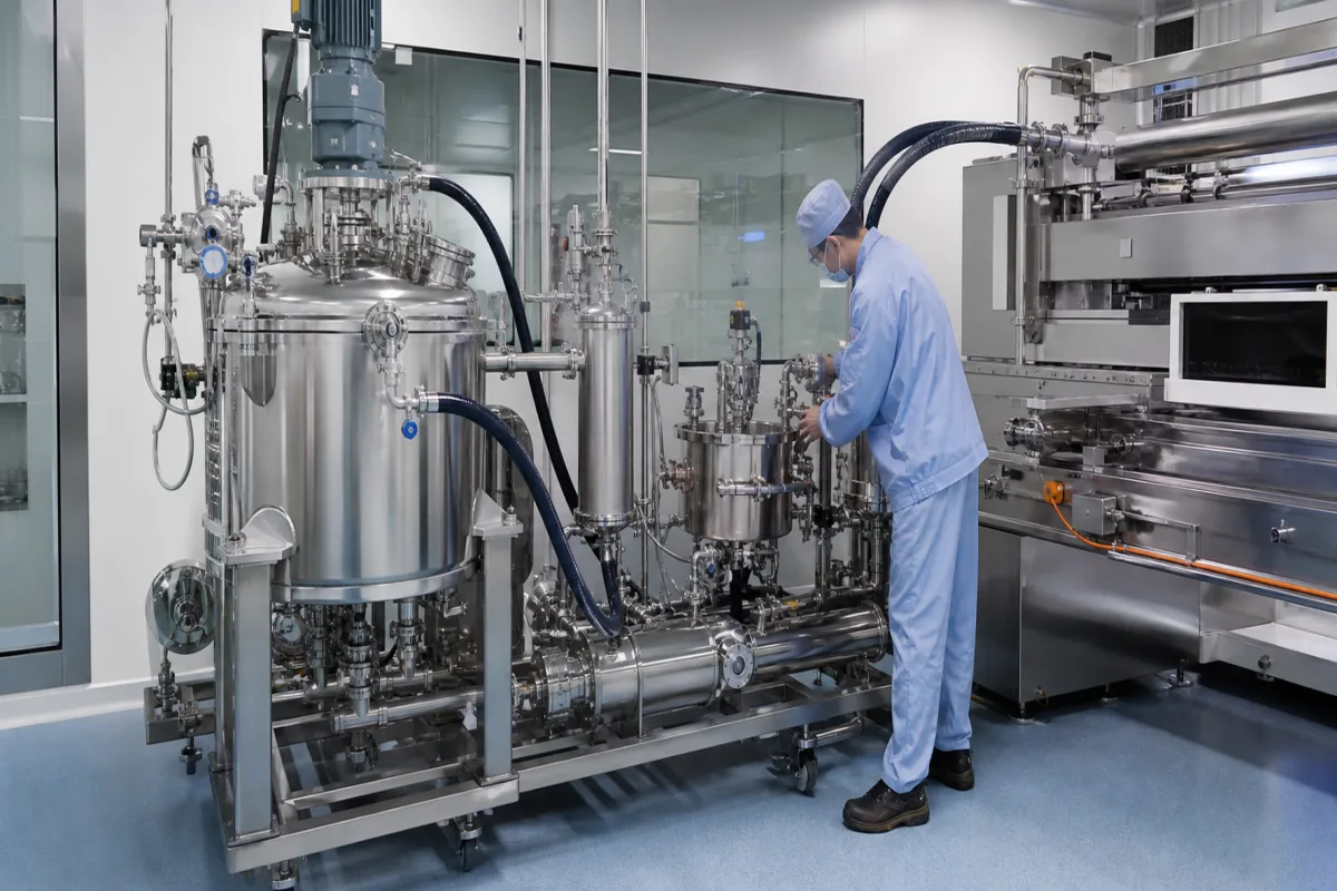
Slurry supply system for battery electrode coating: the tank, de-ironing and metering-pump train that feeds a slot die from the mixer
Electrode slurry feed between mixer and coater · storage and buffer tanks, vacuum defoaming, progressing cavity metering from 5 ml/min to 2 m³/h at ±0.5 %, magnetic de-ironing at 8,000–10,000 Gs and mesh screens
Between the slurry mixer and the coating head sits a train of tanks, magnets, screens and pumps. It decides how steadily the slurry reaches the die, whether bubbles are taken out on the way, and whether metal particles from the powder or from the equipment itself are caught before they end up in the electrode.
Slurry supply between the electrode slurry mixer and the coating head: storage and buffer tanks with slow stirring, vacuum defoaming, magnetic de-ironing and mesh filtration, and the metering pumps that feed slot-die or comma coaters, from laboratory feeders to production pumps. The coating line itself, coating heads, dryers and solvent recovery are covered on the Lithium-ion battery electrode coating machine page, slot-die heads on the Precision slot-die coating applicator page, foil tension through the coater on the Web tension control unit for battery electrode coating page, and slitting tension on the Tension control system for lithium-ion battery electrode slitting and rewinding page. Metering pumps as a product family are covered on the Metering pump page; electrolyte degassing on the Vacuum degassing chamber for lithium-ion battery electrolyte page.
CNFX editorial research · Sources checked October 13, 2026 · 4 sources
Metering slurry to the die: progressing cavity pumps from 5–50 ml/min dispensers to 2 m³/h mini pumps, rated ±0.5 %
NETZSCH's battery brochure presents its NEMO progressing cavity pumps for the coating feed because flow rate is directly proportional to speed and the pumps convey with very low shear; it states accuracy up to ±0.5 % and a viscosity range up to 3,000,000 cP for the range as a whole. [1]
What the pump touches matters as much as how it meters. NETZSCH lists no metal-to-metal contact of wetted parts so that no metal enters the product, a duplex stainless steel rotor with a ceramic rotor for special cases, PTFE and other elastomer stators, and a flexible connecting rod in place of lubricated joints, because a failing joint sleeve can leak lubricant into the slurry and a worn joint can shed metal into it. Seal options run from a single mechanical seal to gland packing, double mechanical seals and seal-less magnetic couplings. [1]
Editorial calculation, with assumed coating values: a 300 mm wide coating at 1 m/min and 200 µm wet thickness needs 0.3 m × 1 m/min × 0.0002 m = 60 ml/min of slurry. That sits inside the MSK-156 feeder's 5.2–186 ml/min range and just above the 5–50 ml/min of one NEMO Dispenser. [2][1] Width, speed and wet thickness for a real line have to come from the coating specification.
4 L 304 stainless airtight reservoir, stirring up to 27 rpm, EPDM stator, SUS316 rotor, 0.5–0.8 MPa compressed gas supply [2]
Give the wet coating width, line speed range and wet thickness so the required flow can be calculated, plus the slurry viscosity and solids content, and ask for the pump's flow at those conditions and its wetted materials.
02
From mixing tank to coater: storage tank, vacuum defoaming and a buffer tank ahead of the metering pump
NETZSCH's process sketches for a battery plant place pumps at each transfer: one or more pumps feed raw materials to the stirring tank, a pump carries the mixed slurry to a storage tank, slurry is defoamed in a vacuum tank, and from storage it passes through a buffer tank to the coating machine. [1]
For the vacuum step, NETZSCH notes that its pumps are reversible and can operate on vacuum vessels to remove bubbles from the fluid. For the last step it shows a mini pump filling the buffer tank and dispenser pumps drawing from it to the coating head, with flow changes made pump by pump or for all pumps at once. [1]
Laboratory feeders compress the same sequence into one unit: MTI's MSK-156 has a pneumatically sealed 4 L reservoir with a slow stirrer at up to 27 rpm, feeding a screw pump that serves MTI's MSK-AFA-DS300 roll-to-roll coater. [2]
State where the slurry is defoamed, the buffer volume ahead of the coater, and whether the tanks are stirred, sealed or under vacuum.
03
Taking iron out before the coater: 8,000–10,000 Gs magnetic rods, 80–120 mesh screens and rods that clean themselves
MTI builds a magnetic de-ironing filtration unit for electrode slurry to be used before coating: the slurry passes a set of permanent magnetic rods and then a mesh filter, removing iron impurities and large particles. [3]
The MSK-FT02 lists a 5 L process capacity, a magnetic field strength of 8,000 Gs with a de-ironing range given as 8,000–10,000 Gs, slurry viscosity up to 15,000 cP, and three mesh screens of 80, 100 and 120 mesh, with 150, 200, 250 and 325 mesh on request. [3]
On a production line the rods load up with captured iron and have to be cleaned. Xiamen Junming Technology's European patent application EP 4 427 845 A1 (published 11 September 2024) describes the prior practice of pulling the magnetic rod out of the slurry and cleaning it by hand, which it calls time-consuming and a risk of corrosion from the slurry and of being clamped by the magnetic rods. Its equipment lifts the rod assembly from an iron removal cylinder in the slurry channel to a cleaning station, where a driven wiper clamps the outer periphery of the rod and cleans the impurities off it; the equipment also includes a collecting piece. [4]
Ask for the field strength at the rod surface, the screen mesh after the magnets, the maximum slurry viscosity the unit passes, and how the rods are cleaned without stopping the feed.
04
Data for an electrode slurry supply system
Paste it into your enquiry below or into an email to a maker, then replace every bracket.
Slurry: [anode or cathode; solvent (NMP or water); solids content; viscosity]
Flow: [coating width; line speed; wet thickness; number of coating lanes or heads]
Tanks: [storage and buffer volume; stirring; vacuum defoaming]
Pumps: [type; flow range; accuracy; wetted materials; seal type]
Filtration: [magnetic field strength; mesh after magnets; rod cleaning]
Interface: [coater make; control signals]
Explore company information and manufacturing capabilities, then discuss the scope of your project with a relevant supplier.
Share this page
Compiled and source-reviewed by the CNFX editorial team.
Each manufacturer above links to the page on that company's own website where the product is listed, with the date we checked it. How we source and review
· Page last updated 13 October 2026
Buyer questions
What pump feeds electrode slurry to a slot die?
NETZSCH offers NEMO progressing cavity pumps for coating feed, citing flow proportional to speed and accuracy up to ±0.5 %; its NEMO Dispenser covers 5–50 ml/min. [1]
How much slurry does a coater need?
It follows from coating width × line speed × wet thickness; at an assumed 300 mm, 1 m/min and 200 µm wet, that is 60 ml/min, within the 5.2–186 ml/min of MTI's MSK-156 feeder. [2]
How is iron removed from battery slurry?
With permanent magnetic rods followed by a mesh screen; MTI's MSK-FT02 uses 8,000–10,000 Gs rods and 80–120 mesh screens for slurry up to 15,000 cP. [3]
Why avoid metal contact in slurry pumps?
NETZSCH states that its battery pumps have no metal-to-metal contact of wetted parts and a flexible rod instead of lubricated joints, so no metal or lubricant enters the slurry. [1]
Sources and what still needs a direct check
Sources checked 2026-10-13. NETZSCH Pumps USA's lithium battery brochure (NEMO pump ranges, wetted design, plant sequence), MTI Corporation's MSK-156 slurry feeder and MSK-FT02 de-ironing filter pages, and Xiamen Junming Technology's patent application on self-cleaning magnetic rods.