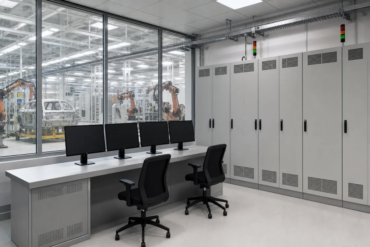
Central control system for robotic body-in-white welding lines
Body-in-white welding lines · Line PLC, operator HMI and I/O network that sequence fixtures and call robots: robots per controller, cycle time, availability, remote I/O count
On a body-in-white line each robot has its own controller for motion, while a central control system decides what happens next: it clamps and unclamps fixtures, checks that parts are present, calls each robot into the fixture, watches for robot-to-robot interference, stops the line on a fault and shows the operator what went wrong. What a buyer has to size is how many robots and devices one controller coordinates, the cycle time and availability it must hold, and how the I/O is networked.
Line and cell control systems for automotive body-in-white welding, brazing and sealing lines: line PLCs or PC-based controllers, operator HMI stations, remote I/O and fieldbus networks, and their interfaces to robot controllers, welding equipment and safety devices. This differs from machine-level PLC motion control (pulse-train or EtherCAT axes on one machine), which is covered on the Industrial control systems page. PLC control cabinets as assemblies, redundant hot-standby PLCs and safety PLCs have their own pages, as do machine control cabinets for OEM machines, on-machine control units to IEC 60204-1, central clutch/brake controls for press lines, arc-furnace process control, vehicle ECUs, multi-loop PID controllers and portable calibration modules; robot controllers themselves and plant MES software are outside this page.
CNFX editorial research · Sources checked October 12, 2026 · 3 sources
Fixture sequencing, robot calls and OEE on one PC-based controller for 21 robots
Automation World describes a body-in-white project by the integrator Sodecia with 21 KUKA robots of 6–210 kg payload. KUKA controllers handle each robot's motion, but the whole welding cell is coordinated by TwinCAT PLC software on a 15-inch panel PC, which runs all sequencing: fixture clamp and unclamp, part detection, error proofing, calling specific robots into fixtures and their tasks. [1]
The same controller handles robot-to-robot interference detection, production counting and OEE tracking, and acts as the HMI for fault detection and annunciation. The cell has 228 devices; EtherCAT carries robot communications, I/O and programmable safety functions, with each major component tied to a safety logic terminal for e-stops and machine monitoring. The article reports a 50% cut in control-system commissioning time and, from the carmaker, an average cycle time of just under 50 s, 72 complex parts per hour and up to 355,000 parts per year. [1]
Editorial calculation: 3,600 s ÷ 50 s = 72 parts per hour, matching the reported rate; 355,000 parts ÷ 72 per hour ≈ 4,930 production hours a year. [1]
Tell the supplier how many robots, fixtures, clamps and sensors one controller must coordinate, which robot brand and interface it must talk to, the cycle time per part, and whether production counts and OEE must be collected on the line controller or passed to a plant system.
02
A laser geometry station: two cabins, 28 robots, three PLCs
Barros and Batalha (University of São Paulo) describe a laser body-framing station of two cabins, one with 16 robots and one with 12, controlled by three PLCs: one per cabin and one switching seven Nd:YAG laser sources between robots. Each cabin was to produce 600 bodies a day across three car models, operate about 290 pneumatic devices that position the body parts, reach 85% availability and hold a cycle time of about 75 s. [2]
Each enclosed cabin is about 400 m³ and is loaded and unloaded by skid roller conveyor. The authors call the PLC the system maestro, synchronising robots, laser sources, other controllers and safety devices such as fences, scanners and light curtains, and list the definition of scan cycle time requirements among the steps for structuring the PLC program. Logic was validated in PLC simulation software before start-up. [2]
Editorial calculation: 600 bodies × 75 s = 45,000 s, or 12.5 h of running time a day; at 85% availability that needs about 12.5 ÷ 0.85 ≈ 14.7 h of scheduled time per cabin. [2]
03
Auto, hand and manual modes and what the operator screen shows first
The same paper sets out three control modes: auto, in which operations run automatically until a fault is detected; hand, used to coordinate more than one station or step through the automatic process; and manual, for single-station jog motions during fault recovery. Because operations depend on each other, any fault stops the whole system until the operator restarts it. [2]
The station HMI runs on an industrial PC with run-time diagnosis and command screens, a screen editor, the PLC program editor and the network configuration editor. The authors advise that information on unplanned stops, which put the station's availability at risk, should be given priority on the run-time screens, and that screens must cover manual operation and recovery from faults. [2]
04
Remote I/O at line scale: 46 PLCs and 2,000–3,000 I/O units
The CC-Link Partner Association describes a vehicle-body line of arc and spot welding robots controlled by 46 PLCs, each with 7 or 8 network master units, and 2,000 to 3,000 remote I/O units across the system. The stated reasons were less wiring, devices grouped into blocks for easier interfacing, shorter on-site installation, and faster transport control over the high-speed network. [3]
Editorial calculation: 46 PLCs with 7–8 masters each is 322–368 master units; 2,000–3,000 remote I/O units over 46 PLCs is about 43–65 per PLC. [3]
Ask the supplier for the network architecture drawing: number of line controllers, masters per controller, remote I/O blocks per station, and how robot controllers, welding controllers and safety devices connect.
05
Send the line, robot and network data together
Paste it into your enquiry below or into an email to a maker, then replace every bracket.
Line: [stations; bodies or parts per hour; cycle time; models run]
Robots: [number; brand; process: spot, arc, laser, sealing]
Devices: [fixtures; clamps and pneumatic devices; sensors]
Controller: [PLC or PC-based; one per cell or per station; programming language]
Network: [fieldbus; masters; remote I/O count]
HMI: [operator stations; modes; fault screens; OEE and counts]
Safety: [fences, scanners, light curtains; safety network]
Targets: [availability; commissioning schedule]
Explore company information and manufacturing capabilities, then discuss the scope of your project with a relevant supplier.
Share this page
Compiled and source-reviewed by the CNFX editorial team.
Each manufacturer above links to the page on that company's own website where the product is listed, with the date we checked it. How we source and review
· Page last updated 13 October 2026
Buyer questions
How many robots can one line controller coordinate?
Published examples include one TwinCAT PLC coordinating 21 KUKA robots in a welding cell, and three PLCs running two laser cabins with 16 and 12 robots. [1][2]
Does the central controller move the robots?
No; in the Sodecia example KUKA controllers handle robot motion while the PLC sequences fixtures, calls robots and tracks counts and OEE. [1]
How large is the I/O on a full welding line?
One CC-Link case describes 46 PLCs and 2,000 to 3,000 remote I/O units for a vehicle-body welding line. [3]
Sources and what still needs a direct check
Sources checked 2026-10-12. Automation World reports an integrator's project with figures supplied by the integrator and carmaker; the São Paulo paper describes one laser station's design targets; the CC-Link case is published by the network's partner association.