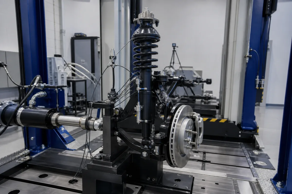
Electronically controlled (semi-active) suspension dampers · Continuously variable versus switched damping, solenoid pressure-regulating valves, response fast enough for each wheel movement, skyhook-type control policies, sensors and controller, testing on a rig
An automotive active suspension damping system — semi-active in the designs described here — uses electronically controlled dampers whose valves change the damping force in real time, under a controller fed by body and wheel motion sensors, to improve ride and body control; fully active systems add a power source that can push as well as resist. Ask three things first: whether the vehicle needs switched or continuously variable damping and how fast it must change, what valve technology and damping range the dampers use, and which sensors, control policy and vehicle interfaces the controller needs.
Electronically controlled shock absorbers and struts with solenoid or similar valves, their controllers and sensors, as systems for passenger and commercial vehicles. Passive shock absorbers, air springs and levelling compressors sold alone, magnetorheological fluid as a material, and complete vehicles are outside this page except where compared.
CNFX editorial research · Sources checked October 11, 2026 · 4 sources
General Motors' US patent 5,163,706 (1992) describes an electro-hydraulic pressure-regulating valve assembly for a hydraulic damper used for semi-active ride control: a solenoid in the valve body controls pressure in a chamber that biases a deflectable disc controlling flow, so fluid pressure — and with it damping — is proportional to the coil current, giving continuously variable damping in real time through a computer controller. It explains that earlier controllable dampers, using solenoids or motors to select settings, were limited in response by small actuators and high friction, could not change quickly enough for the next suspension movement, and offered only a few discrete settings. [1]
The patent presents its compact valve as suitable for mass production on passenger and commercial vehicles, with the damper's reservoir tube, inner cylinder and piston arrangement otherwise conventional. [1]
Editorial note: ask the supplier for the damping-force range against velocity at minimum and maximum current, the valve's step response time measured on a damper rig, and its behaviour if power is lost.
Give the supplier the vehicle type and mass per corner, damper or strut geometry and mounts, required damping range (force against velocity at soft and firm settings), switched or continuous control, response time target, valve type and current range, fail-safe setting, sensors available on the vehicle, controller and network interface (for example CAN), environmental and durability tests, and quantities.
02
Compare valve response times measured on a damper rig
A 2023 Warsaw University of Technology and Lodz University of Technology study built a semi-active damper (PZD-FT) by modifying a Ford Transit van damper with a piezoelectric valve that changes the oil-flow gap between chambers. The authors state that dampers using magnetorheological fluid or standard solenoid valves change their characteristics over the full range in as long as 80–100 ms, and that their damper changed the damping force about five times in about 10 ms (8–10 ms measured) by changing the actuator supply voltage. [4]
Editorial calculation: a 10 ms change is 8 to 10 times faster than the 80–100 ms the authors cite for solenoid and MR designs. At 1 Hz body motion one cycle lasts 1,000 ms, so a 100 ms change takes a tenth of a cycle and a 10 ms change a hundredth. [4]
The piezo valve is a research prototype, while General Motors' patented solenoid valve above is a production-oriented design. The study shows that response time is a measurable figure. Ask each supplier to state the step response of its valve on a damper rig, with the excitation frequency, amplitude and supply range used, and compare offers under the same test conditions. [4][1]
Item reported in the study
Value
Full-range change, MR fluid or standard solenoid valve dampers (cited by the authors)
1 Hz, 30 mm amplitude (range tested 0.5–2.5 Hz) [4]
Vehicle model in the simulation
1,200 kg body, 47,500 N/m springs, axles 1.6 m from centre of gravity [4]
03
Set the control policy, sensors and controller
Lord Corporation's US patent 4,898,264 (1990) states a known semi-active control policy: make the damping coefficient relatively high when the product of the relative velocity across the damper and the absolute velocity of the supported (body) member is positive, and relatively low when it is negative. It notes that dampers may be on/off types or continuously variable types whose on-state force follows the body's absolute velocity, and that electronic devices are used to decide and drive the switching; its own invention performs the switching mechanically with an inertial body to save cost. [2]
Editorial calculation: with assumed damping coefficients of 1,000 N·s/m (soft) and 3,000 N·s/m (firm) at a damper velocity of 0.5 m/s, the force changes from about 500 N to 1,500 N when the controller switches from soft to firm; a continuously variable valve can set any value between, which is why its response time matters for each wheel movement. [2][1]
Editorial note: agree with the supplier which sensors (body accelerometers, wheel or damper position sensors) the control needs, where the control software runs, and how the system is calibrated and validated on the vehicle.
04
Compare passive, active and semi-active isolation
US patent 3,807,678 (Dean Karnopp and Michael Crosby, assigned to Lord Corporation, filed 19 September 1972 and granted 30 April 1974) describes a system it calls semi-active: a passive spring and an instantaneously and continuously variable damper act in parallel between the body and its support, and the damper's force is varied from a sensor signal such as displacement, velocity or acceleration rather than from the damper's own motion alone. [3]
The patent explains the compromise in a passive isolator: it amplifies motion around its natural frequency, set by the spring rate K and the supported mass M, and it isolates only at frequencies above the square root of 2 (1.414) times that natural frequency, so damping that helps near resonance detracts from isolation in the higher range. Fully active isolators avoid this by supplying energy, but the patent notes they need a large auxiliary power source with motors, pumps, fluid reservoirs and servovalves, and respond poorly at high frequencies. [3]
Its claims describe the damper producing a controllable resisting force when the commanded force is opposite to the direction of relative movement, and a substantially non-resisting force when the command is in the same direction — the damper only dissipates energy, which is why a semi-active system needs no large external power source. Claim 4 names a viscous damper with pressure-controlled valve means, the arrangement the General Motors valve later refines. [3][1]
Editorial calculation: for an assumed corner with 400 kg sprung mass on a 25,000 N/m spring, the undamped natural frequency is (1/2π)·√(25,000/400) ≈ 1.26 Hz, so by the patent's 1.414 rule isolation starts at about 1.78 Hz; road inputs between these frequencies are where a controllable damper has to trade body control against isolation. [3]
05
Find semi-active suspension damper manufacturers
Zhejiang Gold lists an "Adaptive Damping System" and Xiamen Kaifa has a product page for active suspension damping systems; ask each which valve principle, response time and fail-safe setting their product has.
06
Damper body, solenoid valve, ECU, motion sensors and fail-safe setting of a semi-active damping system
Control mode, valve principle, response, policy and fail-safe values for a damping system quotation
Published values in this table come from the General Motors and Lord Corporation patents; where neither states a value, the row says what to obtain from the supplier.
Field
What it means and published values
Ask the supplier for
Damping control
Continuously variable vs discrete settings. [1][2]
Find active suspension damping systems manufacturers
2 companies list this product among what they make. Company figures are quoted from each
company's own website; every card states where the relationship came from.
Explore company information and manufacturing capabilities, then discuss the scope of your project with a relevant supplier.
Share this page
Compiled and source-reviewed by the CNFX editorial team.
Each manufacturer above links to the page on that company's own website where the product is listed, with the date we checked it. How we source and review
· Page last updated 13 October 2026
Buyer questions
How does a continuously variable damper change its damping?
In one design a solenoid valve sets fluid pressure in proportion to coil current, controlling a disc that meters flow, so damping follows the current in real time. [1]
What is the skyhook-type control policy?
Damping is high when the product of the damper's relative velocity and the body's absolute velocity is positive, and low when it is negative. [2]
Why did older adjustable dampers fall short?
Small actuators and friction limited their response, so a setting could not change in time for the next suspension movement. [1]
What makes a damping system semi-active rather than fully active?
A semi-active system pairs a passive spring with a continuously variable damper that can only resist relative motion, so it needs no large external power source; a fully active isolator supplies energy through motors, pumps and servovalves. [3]
Sources and what still needs a direct check
Sources checked 2026-10-11. Three patents frame this page: the Karnopp–Crosby patent that defines semi-active isolation, General Motors' solenoid damper valve and Lord Corporation's control policy. They describe their applicants' concepts; performance for your vehicle must come from the supplier's rig and vehicle test data. A 2023 Warsaw and Lodz University of Technology study adds measured response times for a piezo-valve damper against solenoid and MR designs.