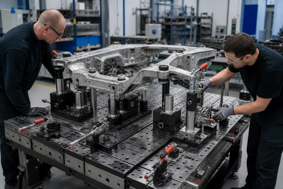
Modular tooling fixtures on dowel-hole grid plates: hole accuracy, off-grid adjustment with eccentric pins, and rebuilding a fixture from its recorded hole addresses
Fixtures assembled from reusable elements on a grid of bushed dowel holes · plates held to ±0.0004 in between hole centres, a 50 mm pitch bridged by a set of 64 eccentric dowel pins in 0.05 mm steps, labelled hole addresses for rebuilding a setup, and diamond pins turned to suit the part
A modular fixture is built rather than machined: tooling plates or blocks carry a grid of precision holes, and standard risers, locators, supports and clamps are pinned and screwed into them, then taken apart for the next job. The accuracy of the result rests on the hole grid, on how a locator is placed between grid positions, and on whether the same build can be reproduced next time.
Hole-type (dowel-pin) modular fixturing systems for machining, inspection and low-volume assembly of parts such as cast or fabricated chassis components: grid tooling plates and blocks with bushed locating holes and tapped holes, locating screws and dowel pins, eccentric pins for off-grid positions, diamond locating pins, and plate-to-machine location. Welding tables with 16, 22 and 28 mm bore systems, weld datums and distortion control are covered on the Welding fixtures page; dedicated machining fixtures and zero-point pallets on the Workpiece fixture for machining cast housings page; fixed sheet-metal assembly fixtures on the Assembly Fixture page; floor-pan pallet fixtures on the Pallet-mounted positioning fixture page; toggle clamps on the Toggle-clamp clamping fixture for welding page.
CNFX editorial research · Sources checked October 13, 2026 · 4 sources
The hole grid sets the accuracy: ±0.0004 in between centres, alternating dowel and tapped holes, and addresses for every hole
Bluco's modular system, aimed at low-volume, high-mix work, alternates dowel holes and tapped holes on its fixture plates and states an accuracy of ±0.0004 in between centres. Baseplates can be fitted to tombstones for horizontal machining, and a ball-lock option lets fixtures be set up off the machine for quick changeover. [1] Editorial calculation: 0.0004 in × 25.4 ≈ 0.010 mm.
Carr Lane combines both functions in one hole: each multipurpose hole on its tooling plates and blocks has a precision alignment bushing on top and a threaded insert below, so a locating screw both locates and fastens a component. The grid is lettered in one direction and numbered in the other, and block faces carry Roman numerals, so the mounting hole of each component can be recorded as permanent documentation of the setup. [3] Carr Lane sells the same modular components in three system sizes, Mini, Standard and Heavy, to cover a range of workpiece sizes. [3]
Ask for the between-centre tolerance of the hole grid as a figure, whether holes are bushed and hardened, the hole and thread size of the system, and how hole addresses are marked on plates and blocks.
02
Positions between grid holes without slots: 64 eccentric dowel pins in 0.05 mm steps up to 3.15 mm across a 50 mm pitch
The CATIC and Qing Yang Machine Works patent states the trade-off of the two system types: slots give adjustability along an axis, holes give adjustability around one, but slot-type systems cannot adjust continuously where slots cross and need rigging and indicating to set precisely. Its answer for a hole-type system with a 50 mm grid pitch and 25 mm grid coordinate distance is a set of eccentric dowel pins and a pin-adjusted structure. [2]
Each pin has a lower cylinder in the plate hole and a smaller upper cylinder offset from it on a prism. With a maximum eccentricity of 3.15 mm, chosen so that four times the eccentricity is at least a quarter of the 50 mm pitch, and 64 pins in 0.05 mm increments, a locator can be moved along an axis continuously in 0.05 mm steps without rigging or indicating; the apertures of the pin-adjusted structure are 43.75 mm apart. [2] Editorial calculation: 4 × 3.15 = 12.6 mm, which covers the 12.5 mm that is a quarter of the 50 mm pitch.
Ask how the system places a locator between grid holes, by slots, eccentric pins or adjustable elements, and the step size and range of that adjustment.
03
Locating the workpiece and the plate: diamond pins turned to the bore line, and a round and a diamond key on the subplate
Carr Lane's modular fixturing patent addresses parts located on two parallel bores, such as castings and forgings. A diamond-shaped pin, relieved on two sides, tolerates variation in bore spacing only when the line through its arcs is perpendicular to the line joining the bores; the patent's adaptors hold diamond pins at a chosen angle, including 45 degrees, on a drilled and tapped base plate, with adaptor heights chosen to bring the part to its machining level. [4]
For the plate itself, Carr Lane locates rectangular tooling plates on a T-slotted table with two locating keys in the centre slot, or as quick-change plates on a subplate using one round and one diamond (relieved) key for location without binding; on a machining-centre pallet, JIS-type mounting pulls the plate against two ground reference edges at 90 degrees with three screws. [3]
Ask which locating pins are round and which are diamond, how their angle is set and fixed, and how the fixture plate is located on the machine, table, subplate or pallet.
04
What to send for a modular tooling fixture kit
Paste it into your enquiry below or into an email to a maker, then replace every bracket.
Parts: [part family; size and weight; locating bores or surfaces]
Process: [machining, inspection or assembly; machine or table]
Grid: [hole pitch; between-centre tolerance; bushed or plain; thread size]
Plates: [plates, cubes or angle plates; mounting to table, subplate or pallet]
Elements: [risers, supports, round and diamond pins, eccentric pins, clamps]
Records: [hole addressing; setup documentation for rebuilds]
Explore company information and manufacturing capabilities, then discuss the scope of your project with a relevant supplier.
Share this page
Compiled and source-reviewed by the CNFX editorial team.
Each manufacturer above links to the page on that company's own website where the product is listed, with the date we checked it. How we source and review
· Page last updated 13 October 2026
Buyer questions
How accurate are modular fixture plates?
Bluco states ±0.0004 in (about 0.010 mm) between centres for plates with alternating dowel and tapped holes. [1]
How do you place a locator between grid holes?
One patented method uses a set of 64 eccentric dowel pins in 0.05 mm increments up to 3.15 mm, covering a 50 mm grid without slots or indicating. [2]
How is a modular fixture rebuilt the same way later?
Carr Lane labels hole grids with letters and numbers, and block faces with Roman numerals, so each component's mounting hole can be recorded. [3]
Why turn a diamond locating pin?
A diamond pin only allows for bore-spacing variation when its arcs are perpendicular to the line between the bores; Carr Lane's patented adaptors hold it at a chosen angle. [4]
Sources and what still needs a direct check
Sources checked 2026-10-13. Plate accuracy comes from a Cutting Tool Engineering product item on Bluco's system; off-grid adjustment from a CATIC and Qing Yang Machine Works patent; multipurpose holes, grid addresses and plate location from Carr Lane's technical pages; diamond pin adaptors from a Carr Lane patent.