Editorial Technical Reference

Automotive Battery Management System

This page explains how Automotive Battery Management System is classified within Motor Vehicle Manufacturing. Technical values and manufacturer relationships are research references; confirm the current specification and supplier evidence for each order.

Technical Definition & Core Assembly

The Automotive Battery Management System (BMS) is an electronic control unit (ECU) designed for electric and hybrid vehicles.
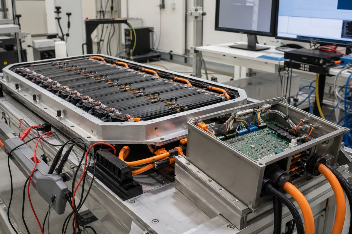
Representative product image. Confirm appearance and specifications with the manufacturer.

Product Specifications

Technical details and manufacturing context for Automotive Battery Management System

Definition
The Automotive Battery Management System (BMS) is an electronic control unit (ECU) designed for electric and hybrid vehicles. It continuously monitors the state of charge (SOC), state of health (SOH), voltage, current, and temperature of individual battery cells within a high-voltage traction battery pack. The system ensures safe operation, optimizes charging and discharging cycles, balances cell voltages to maximize pack lifespan, and communicates vital data to the vehicle's main control systems. It is a foundational component for vehicle safety, performance, and range.

This BMS supports battery packs with an operating voltage range of 9–36 V and can manage up to 96–192 cells in series. It uses a CAN 2.0B communication interface (per ISO 11898) to relay data. The system operates in ambient temperatures from -40°C to 85°C and achieves a cell voltage measurement accuracy of ±5 mV. Current measurement accuracy for SOC estimation is ±1% of full scale, and after calibration, SOC accuracy is ±3%. It measures insulation resistance from 0 to 10 MΩ to detect leakage. In sleep mode, quiescent current is less than 1 mA. The housing is rated IP67 (per IEC 60529) for under-hood mounting. Weight ranges from 0.5 to 2.5 kg, and dimensions are customizable within 150×100×30 mm to 300×200×60 mm (L×W×H).

Constructed with an FR4 PCB, a microcontroller IC, sensor ICs for voltage and temperature, connectors, and an aluminum housing, the BMS is a robust device for demanding automotive environments. It is important to verify model-specific values and standards with the legal manufacturer or supplier, as the listed parameters are reference ranges for typical configurations.
Working Principle
The BMS uses a network of sensors and a microcontroller to measure cell parameters. Voltage and temperature sensors on each cell provide data, which the microcontroller processes to determine battery state. It calculates SOC, SOH, and other metrics, then executes control logic for cell balancing, thermal management, and power limits. The system communicates via CAN bus to the vehicle's main control systems, enabling coordinated operation. It also monitors insulation resistance to detect potential leakage, enhancing safety.
Common Materials
FR4 PCB, microcontroller IC, sensor ICs (voltage, temperature), connectors, aluminum housing
Technical Parameters
ParameterTypical rangeNotes & selection driver
Operating Voltage RangeRequired9–36 VSupported battery pack voltage range
Maximum Cell CountRequired96–192 SMax number of cells in series supported
Communication InterfaceRequiredCAN 2.0B N/APrimary communication protocolISO 11898
Operating TemperatureRequired-40–85 °CAmbient operating temperature range
Cell Voltage Measurement AccuracyRequired±5 mVAccuracy of individual cell voltage measurement
Current Measurement Accuracy±1 % FSFor SOC estimation
State of Charge Accuracy±3 %After calibration
Insulation Resistance Measurement Range0–10 Detects leakage
Quiescent Current<1 mAIn sleep mode
Ingress Protection RatingIP67For under-hood mountingIEC 60529
Weight0.5–2.5 kgDepends on configuration
Dimensions (L×W×H)150×100×30 – 300×200×60 mmCustomizable

Ranges are indicative industry figures for RFQ preparation, not a supplier commitment. Confirm every value and standard with the legal manufacturer before ordering.

Components / BOM
  • Main Control Unit (MCU)
    Central processor for data calculation and system control
    Material: Silicon (IC)
  • Cell Monitoring IC Part
    Measures voltage and temperature of individual battery cells
    Material: Silicon (IC)
  • Current Sensor Part
    Measures total pack current
    Material: Various (Hall-effect sensor, shunt resistor)
  • Isolation Monitor Part
    Monitors electrical isolation between high-voltage battery and vehicle chassis
    Material: Silicon (IC)
  • Balancing Circuit Part
    Passive or active circuit to equalize charge between cells
    Material: Resistors, MOSFETs, PCB traces
  • Communication Transceiver Part
    Hardware for vehicle network communication (e.g., CAN transceiver)
    Material: Silicon (IC)
  • Enclosure Part
    Protects electronics from environment and provides mounting
    Material: Aluminum or plastic

Industry Taxonomies & Aliases

Commonly used trade names and technical identifiers for Automotive Battery Management System.

Industrial Ecosystem & Supply Chain Structure

Complementary Systems
Downstream Applications
Specialized Tooling

Application Fit & Sizing Matrix

Operational Limits
pressure: Atmospheric (sealed enclosure, IP67 rating typical)
other spec: Voltage Range: 9V to 60V DC (typical for 12V/48V systems), Communication: CAN/LIN bus, Sampling Rate: 1-10 Hz per cell
temperature: -40°C to +85°C (operational), -40°C to +125°C (storage)
Media Compatibility
✓ Lithium-ion battery packs (NMC, LFP, LTO chemistries) ✓ Lead-acid battery banks (AGM, Gel, Flooded) ✓ Nickel-metal hydride (NiMH) battery arrays
Unsuitable: High-vibration industrial machinery without additional damping (exceeds typical automotive vibration specs)
Sizing Data Required
  • Total battery pack voltage and cell count
  • Maximum continuous and peak current requirements
  • Required communication protocol (CAN, LIN, Ethernet) and diagnostic features

Reliability & Engineering Risk Analysis

Failure Mode & Root Cause
Cell Voltage Imbalance
Cause: Uneven aging or degradation of individual battery cells due to manufacturing variations, temperature gradients, or inconsistent charging/discharging cycles, leading to reduced capacity and potential thermal runaway.
BMS Communication Failure
Cause: Corrosion or physical damage to wiring harnesses and connectors from environmental exposure (moisture, vibration, thermal cycling), or software glitches disrupting data exchange between the BMS and vehicle systems.
Maintenance Indicators
  • Dashboard warning lights (e.g., battery/check engine light) or error messages indicating BMS faults or cell imbalance
  • Audible alerts (e.g., beeps) from the vehicle or visible signs like battery swelling, leakage, or abnormal heat emission from the battery pack
Engineering Tips
  • Implement regular diagnostic scans using OEM-specific tools to monitor cell voltages, temperatures, and state-of-charge metrics, enabling early detection of imbalances or communication errors.
  • Ensure proper thermal management by maintaining clean cooling vents/fans, avoiding extreme temperature environments, and following manufacturer-recommended charging protocols to minimize cell stress.

Indicative industry ranges for design and RFQ preparation. Confirm the exact figures and applicable standard with the manufacturer before specifying.

Compliance & Manufacturing Standards

Applicable Standards
ISO 26262:2018 (Functional Safety) IEC 62133-2:2017 (Safety of Secondary Cells and Batteries) UN 38.3 (Transportation Safety Testing)

Quoted from the published standard.

Manufacturing Precision
  • Cell Voltage Measurement: +/- 0.5%
  • Temperature Sensing: +/- 1°C
Quality Inspection
  • HIL (Hardware-in-the-Loop) Testing
  • Environmental Stress Screening (ESS)

Manufacturers of Automotive Battery Management System

Manufacturer profiles associated with Automotive Battery Management System.

Sourcing Automotive Battery Management System from China?
Tell us your specification and target quantity — we will match it against manufacturer records and come back with the factories that fit.
Request manufacturers We manufacture this

Manufacturer listings support early research and capability understanding. They are not certification, ranking, or transaction guarantees.

Technical documentation
Request current drawings, revision history, and a signed specification sheet.
Manufacturing capability
Verify equipment lists, process limits, capacity, and representative production evidence.
Inspection readiness
Confirm test methods, calibrated equipment, sampling plans, and traceable reports.
Supplier transparency
Check the legal entity, factory address, ownership, certifications, and direct contacts.

CNFX does not score or rank suppliers. Buyers must verify all claims and documents with the legal manufacturer before ordering.

Supply Chain Commonly Integrated Components

Chassis Assembly Station

A specialized workstation within an automotive assembly line where the vehicle chassis is assembled and integrated with major components.

Explore Specs →
Modular Tooling Fixtures

Interchangeable, standardized fixtures used to precisely position and secure chassis components during assembly operations.

Explore Specs →
Automated Material Handling System

Automated system for transporting, positioning, and feeding materials within a vehicle body assembly line

Explore Specs →
Assembly Fixture

Specialized tooling device used to precisely position and secure vehicle components during assembly operations.

Explore Specs →

Frequently Asked Questions

What is the operating voltage range of this BMS?

The supported battery pack voltage range is 9–36 V. This is a reference range; confirm the exact range for your specific model with the manufacturer.

How many cells can this BMS manage?

It supports up to 96–192 cells in series. The actual number depends on the configuration, so verify with the supplier.

What communication interface does it use?

It uses CAN 2.0B, which is standardized under ISO 11898. This allows integration with vehicle networks.

What is the ingress protection rating?

The housing is rated IP67 per IEC 60529, suitable for under-hood mounting. This rating indicates protection against dust and temporary immersion in water.

Data Basis

Editorial classification, named public sources where available, and source-reviewed manufacturer records.

Preliminary Technical Classification
This page supports structured research, RFQ preparation, and supplier evaluation. It does not replace buyer-led supplier qualification, standards review, or technical approval.
Buyer enquiry

Request manufacturing insight for Automotive Battery Management System

Ask for use case, specification boundaries, supplier type, and RFQ preparation information for this product.

Where it goes
Straight to the CNFX editorial desk, and to the manufacturer if this product is linked to a claimed profile. Nothing is broadcast to a supplier list.
Your details stay here
We do not sell or rent enquiry data, and we do not add you to a mailing list. Used only to answer this request.
No commission, no middleman
CNFX is a directory. We take no cut of any order and never negotiate on a supplier's behalf.
What we don't claim
A listing is not an endorsement. Qualify every supplier and verify every figure yourself before ordering.

Your business information is used only to process this request.

Thank you! Your message has been sent. We'll respond within 1–3 business days.
Sorry, we couldn't send your message. Please try again, or email us at contact@cnfx.com.

Need to Manufacture Automotive Battery Management System?

Compare manufacturer profiles with relevant product and process capability.

Previous Product
Vehicle Assembly Unit
Last Product
Get QuotesChat