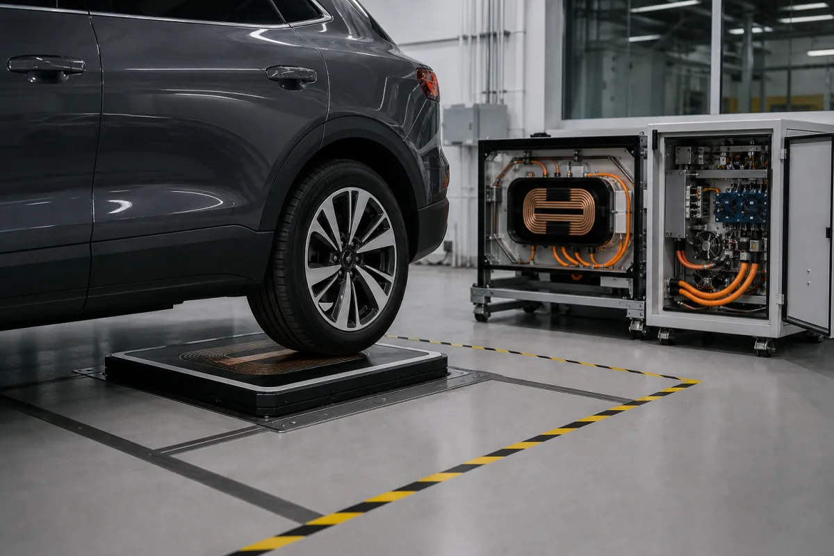
Wireless charging for electric vehicles · ground and vehicle coil assemblies, SAE J2954 interoperability, EMC and EMF requirements, stationary surface-mounted charging up to 11.1 kVA for light-duty vehicles, and high-power research systems transferring 120 kW across a six-inch gap
An automotive wireless power transfer (WPT) system charges an electric vehicle without a cable: power electronics on the ground side convert grid power to high-frequency alternating current in a ground coil, whose magnetic field crosses an air gap to a coil under the vehicle, where it is rectified to charge the battery. Ask three things first: which standard and power class the system meets for interoperability and safety, what air gap and parking alignment it tolerates, and what end-to-end efficiency and emissions it achieves.
Stationary wireless charging systems for electric vehicles: ground assemblies (pads and power electronics) and vehicle assemblies (coils and rectifiers) for light-duty and commercial vehicles. Conductive chargers, dynamic in-road charging, and consumer-device wireless chargers are outside this page except where compared.
CNFX editorial research · Sources checked October 12, 2026 · 4 sources
SAE J2954 (the 2020 revision's summary, with a 2022 revision listed as latest) establishes criteria for interoperability, electromagnetic compatibility, EMF, minimum performance, safety and testing for wireless power transfer to light-duty plug-in electric vehicles. Its charging levels are based on SAE J1772 conductive AC levels with some variations, and it aims at a worldwide WPT standard up to 11.1 kVA. That version covers unidirectional grid-to-vehicle charging, stationary (not in-motion) use and above-ground surface-mounted installations only; it notes that vehicles charged wirelessly under J2954 should also be chargeable conductively under J1772, and that emissions requirements and test procedures are controlled by regulatory bodies. Interoperability was developed by testing candidate designs on a standard test station, defining reference devices for judging products. [1]
Editorial note: ask the supplier which J2954 revision and power class the ground and vehicle assemblies are tested to, which reference devices they were tested against, and which national EMC and EMF regulations the product has been certified to.
Give the supplier the vehicle type and battery, required charging power, standard and revision (e.g., SAE J2954), ground clearance and air gap range, parking alignment tolerance and assistance, installation (surface-mounted), grid supply, communication with the vehicle, EMC/EMF certifications required, foreign-object and living-object detection needs, ingress protection and load rating of the ground pad, and service terms.
02
Understand coil, gap and efficiency
Oak Ridge National Laboratory reported a 120 kW laboratory wireless charging system that transferred power across a six-inch air gap between two magnetic coils at 97% efficiency, which it called comparable to wired high-power fast chargers. Its architecture converts grid energy to high-frequency alternating current to create the magnetic field; after transfer to the secondary coil, power is converted back to direct current for the vehicle battery. ORNL co-optimised the coil design with silicon carbide power electronics to keep the system compact, avoid heating and minimise transfer losses, after earlier demonstrating a 20 kW system. [2]
Editorial calculation: at 97% efficiency, 120 kW of transfer loses about 120 × 0.03 = 3.6 kW as heat in coils and electronics; six inches is about 152 mm. At an 11 kW level, a 60 kWh battery would need roughly 60 / 11 ≈ 5.5 hours from empty, before losses. The battery size and 11 kW level are assumed examples.
03
Ask for measured efficiency and fields across gap and offset
Idaho National Laboratory tested a 3.3 kW wireless charging system (Evatran's PLUGLESS Level 2: 208 to 240 V AC input, 30 A circuit breaker, 100 mm nominal coil gap) in 2013. At 3.3 kW output and 100 mm gap it drew 28 A rms at 208 V AC with a power factor of 0.65, operated at 19.5 kHz and delivered 214 V DC at 15.4 A. INL defines system efficiency as energy out of the vehicle adapter divided by energy into the control panel; it varied with coil position as follows. [4]
Fields measured centred in the 100 mm gap, 0.8 m from the secondary coil centre along the Y axis, were 12.9 A/m and 22.1 V/m with the coils aligned, with maxima of 21.9 A/m and 35.2 V/m at offset coil positions. [4]
Editorial calculation: 208 V × 28 A × 0.65 ≈ 3.79 kW in and 214 V × 15.4 A ≈ 3.30 kW out give about 87%, in line with the nominal figure. The 21.9 A/m maximum at 19.5 kHz is above the 21 A/m ICNIRP general-public reference level for 3 kHz–10 MHz shown above. Ask for efficiency and field maps across gap and offset. [4][3]
The ICNIRP 2010 guidelines for time-varying electric and magnetic fields (1 Hz to 100 kHz) set reference levels as unperturbed rms values. For the 3 kHz–10 MHz range, the general-public reference levels are 83 V/m electric field strength, 21 A/m magnetic field strength and 2.7 × 10⁻⁵ T (27 µT) magnetic flux density; the occupational levels are 170 V/m, 80 A/m and 1 × 10⁻⁴ T (100 µT). The guidelines note that above 100 kHz, radiofrequency-specific reference levels need to be considered as well. [3]
The basic restriction behind these levels is an internal electric field of 1.35 × 10⁻⁴ f V/m for the general public and 2.7 × 10⁻⁴ f V/m for workers in this range (f in Hz), and the reference levels are set so that meeting them keeps exposure within the basic restrictions. [3] SAE J2954 lists EMF among the criteria it establishes for light-duty wireless charging. [1]
Editorial calculation: at an example operating frequency of 85 kHz, the general-public basic restriction is 1.35 × 10⁻⁴ × 85,000 ≈ 11.5 V/m internal field. Ask the supplier for the operating frequency and for measured flux density at the vehicle edge, in the cabin and at ground level beside the pad, compared with the 27 µT reference level.
Exposure (3 kHz–10 MHz)
E-field
H-field
Flux density B
General public
83 V/m
21 A/m
27 µT
Occupational
170 V/m
80 A/m
100 µT
Request the EMF test report: operating frequency, measurement positions, and maximum flux density against the ICNIRP reference levels or the limits your market applies.
05
Stationary J2954 pads, high-power research systems and in-road charging
Light-duty systems under SAE J2954 are stationary, surface-mounted and grid-to-vehicle at levels up to 11.1 kVA; research systems such as ORNL's reach 120 kW for faster charging, and dynamic in-road charging is a future topic in both sources. [1][2]
06
Grid electronics, coil pair and rectifier along the power path
The rows follow the ORNL power path from grid electronics through the coil pair to the vehicle rectifier; the air gap is where test reports differ, six inches at ORNL against 100 mm at INL. [2][4]
Explore company information and manufacturing capabilities, then discuss the scope of your project with a relevant supplier.
Share this page
Compiled and source-reviewed by the CNFX editorial team.
Each manufacturer above links to the page on that company's own website where the product is listed, with the date we checked it. How we source and review
· Page last updated 13 October 2026
Buyer questions
What does SAE J2954 cover?
Interoperability, EMC, EMF, minimum performance, safety and testing for wireless charging of light-duty plug-in vehicles; the 2020 revision covers stationary, surface-mounted, grid-to-vehicle charging up to 11.1 kVA. [1]
How efficient can wireless EV charging be?
ORNL reported 97% efficiency at 120 kW across a six-inch air gap in a laboratory demonstration. [2]
Can a wirelessly charged car still use a plug?
SAE J2954 notes that, in the near term, vehicles charged wirelessly under J2954 should also be chargeable by SAE J1772 plug-in chargers. [1]
What magnetic field level applies near a wireless charging pad?
ICNIRP 2010 sets a general-public reference level of 27 µT (21 A/m) for 3 kHz–10 MHz, and 100 µT for occupational exposure. [3]
How much does coil gap change wireless charging efficiency?
In Idaho National Laboratory's test of a 3.3 kW system, system efficiency ranged from 86.1% to 88.8% at a 100 mm gap and from 86.2% to 89.2% at 110 mm, depending on coil position. [4]
Sources and what still needs a direct check
Sources checked 2026-10-12. SAE J2954 is an SAE International standard, cited from its public summary (Internet Archive copy of the 2020 revision page); ORNL is a US Department of Energy national laboratory reporting its own demonstration (Internet Archive copy).