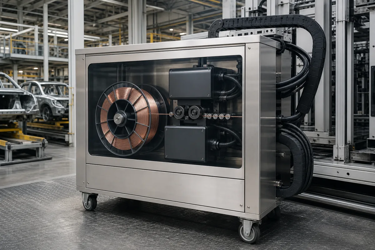
Wire feed system (the wire supply from drum or spool to the feeder of a welding robot)
Wire supply for robotic MIG/MAG welding cells · bulk drums or spools, cast and helix, drum payoff and straighteners, conduit length and bends between drum and robot feeder, feed-assist motors, and push versus push-pull for aluminium
A welding robot stops when its wire stops. The wire feed system is everything between the wire package and the torch: the drum or spool, its payoff and straighteners, the conduit to the feeder, the feeder itself and, for soft wires, a second drive in the torch. Specify it by how much wire the cell uses between changes, how far and along what path the wire travels, and which wire it is.
Wire supply and feeding for robotic and automated MIG/MAG welding: bulk drums and spools, payoff and straightening accessories, conduits and liners between package and feeder, feed-assist drives and push-pull arrangements. Bench, boom and suitcase feeders for semi-automatic welding are covered on the Wire feeder unit (MIG/MAG welding wire feeder) page; cable routing over or through the robot arm on the Robotic arm for welding page; complete cells on the Trailer frame welding robot page.
CNFX editorial research · Sources checked October 12, 2026 · 3 sources
Scott Huber of Abicor Binzel describes the trade-off. Drum systems "allow for more wire due to their size", so high-usage cells need fewer wire changes; a spool "is often times no more than 30 pounds" and needs more frequent changes but is easier to handle. With a drum "you will have to deal with helix of the wire", and drums moved by forklift can have the winding inside disturbed; a spool gives a more consistent, straight feed, with the cast to manage instead. [1]
Lincoln Electric's wire delivery guide lists round drums of 250/300 kg (520 mm), 500 kg (670 mm) and 600 kg (750 mm) and a 136 kg GEMPAC/ALUPAC pack (610 mm), and says drums carry a "Mexican hat" that holds the wire and gives correct unwinding; they should be lifted by their belts with a lifter and moved on carts or dollies. [2]
Editorial calculation: a 30 lb spool is about 13.6 kg, so one 500 kg drum holds the wire of about 37 such spools. [1][2]
Lincoln Electric warns that excessive bending of the conduit from the drum "will affect wire feeding performance negatively", and offers straighteners and direct-pull or orbital-arm kits to straighten the wire leaving the drum. For mild steel solid wire, "a conduit length over 5 meters between the drum and the feeding unit requires a special setup": longer conduits increase friction between wire and liner, and "A wire feed assist motor together with physically constraining the conduit to avoid excessive spatial vibration" can provide the feeding force. Its feed-assist unit is listed as feeding wire up to 30 m. [2]
Draw the route from wire package to robot feeder with lengths and bends, and give the wire type, diameter and package, so the supplier can say whether a feed assist, low-friction liner or straightener is needed.
03
Soft wires: push or push-pull
Bob Jansen's FenderBender article on aluminium welding gives the limits for soft wire: "With push feeders, the liner length must usually be limited to about 3 meters (10 ft.)" because aluminium wire tends to buckle and bind at the drive rolls and birdnest, whereas "A push-pull feeder can have a liner more than 9 m (30 ft.) long", with drive rolls in both the cabinet and the gun, at the cost of complexity and sometimes a separate feed cabinet. [3]
Lincoln Electric lists separate polymer liners for stainless steel and aluminium, with a low friction coefficient. [2]
04
Robot wire feed details
Paste it into your enquiry below or into an email to a maker, then replace every bracket.
Wire: [material; diameter; solid or cored]
Use: [kg per shift per robot]
Package: [spool; drum size; pack type]
Route: [conduit length; bends; height]
Feeding: [push; push-pull; feed assist]
Accessories: [payoff hat or arm; straightener; liner type]
Handling: [drum lifter; dolly]
Robot side: [feeder location; torch]
Explore company information and manufacturing capabilities, then discuss the scope of your project with a relevant supplier.
Share this page
Compiled and source-reviewed by the CNFX editorial team.
Each manufacturer above links to the page on that company's own website where the product is listed, with the date we checked it. How we source and review
· Page last updated 13 October 2026
Buyer questions
Drum or spool for a robot cell?
Drums hold more wire so cells stop less to change; spools of about 30 lb handle more easily and feed with less helix, according to Abicor Binzel. [1]
How long can the conduit from the drum be?
Lincoln Electric says mild steel solid wire through more than 5 m of conduit needs a special setup with a feed assist motor and constrained conduit. [2]
Why do aluminium wires need push-pull?
Soft aluminium wire buckles and birdnests in long liners; FenderBender puts push feeders at about 3 m of liner and push-pull at more than 9 m. [3]
How should drums be handled?
Lincoln Electric says to lift them by their belts with a lifter and move them on carts or dollies. [2]
Sources and what still needs a direct check
Sources checked 2026-10-12. Abicor Binzel publishes a blog on robotic wire feeding; Lincoln Electric publishes a wire dispensing and handling guide; FenderBender published an article on aluminium welding equipment.