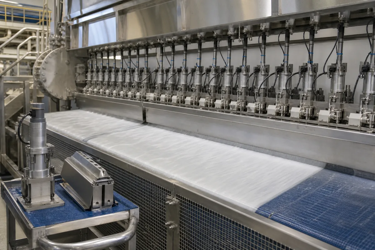
Slice adjustment system: setting the full-width slice opening and lip setback of a paper machine headbox
Whole-width slice geometry on a paper machine headbox · raising the upper lip beam, fine-setting the lip strip, moving the setback, and measuring the opening b and setback L together
A headbox slice adjustment system sets the geometry of the slice across the whole machine width: how far the upper lip stands above the apron (the slice opening, b), and how far the lip tip sits back from the apron tip (the setback, L). Those two settings fix the thickness and angle of the jet and where it lands on the forming fabric. The system is the lip beam and its lifting or swivelling drive, the fine-adjustment mechanism carrying the lip strip, any horizontal adjustment of the lip or apron, and the gauges used to measure b and L.
Whole-width (macro) adjustment of the headbox slice on paper and board machines: upper lip beam lifting or swivelling drives, fine adjustment of the lip strip, setback adjustment of the lip relative to the apron, trajectory-control lips, and devices for measuring slice opening and setback. Local cross-direction profiling of the lip bar by rows of spindle actuators is covered on the Headbox slice lip and its profile actuators page. The headbox as a whole, including flow from inlet to jet, jet-to-wire speed and dilution profiling, is covered on the Paper machine headbox page.
CNFX editorial research · Sources checked October 12, 2026 · 4 sources
Slice opening b, setback L and the ratio that sets the jet angle
Paperchine's US 9,909,850 B2 states that the angle at which the stock jet strikes the fabric is determined by the ratio L/b, where L is the setback of the slice lip from the apron tip and b the slice opening. With L/b near 0.5 the jet strikes at a relatively steep angle, called pressure forming; with L/b of 1 or more it runs nearer parallel to the fabric for longer, called velocity forming. Because the lip can move up and down and also rotate, moving it upstream or downstream changes the impingement point and noticeably affects sheet formation. [1]
Zhao and Kerekes, in a 2017 BioResources review, describe the slice as setting two properties of the jet: its angle and its contraction coefficient Cc. The jet thickness is Cc × b, and Cc can be as small as 0.62, so taking the slice opening as the jet thickness can give a significant error in the calculated headbox flow. They record Nelson's 1960 finding that, without gravity, jet contraction and outflow angle depend on two ratios: the bottom lip extension to slice opening, L/b, and the slice opening to the upstream channel size, b/B; explicit equations for the angle and Cc are given in TAPPI TIP 0410-02, 03 and 04. [4]
Editorial calculation: at a 0.75 in (19.1 mm) opening, one of the nominal openings in the Paperchine patent, a Cc of 0.62 gives a jet about 0.47 in (11.8 mm) thick; using b instead of Cc × b would overstate the flow by about 61% (1 ÷ 0.62). For the patent's worked example of b about 0.49 in and setback 0.7 in, L/b is about 1.4, in the velocity-forming range it describes. [1][4]
Tell the supplier the forming type you run (pressure or velocity forming), the slice opening range across your grades, the setback range needed, and whether L is measured from the lip tip to the apron tip on your headbox.
02
Coarse lift of the upper lip beam and a 10–25 mm fine range on the lip strip
In Valmet's US 3,976,539 A, the slice is formed between a fixed lower lip beam and an adjustable upper lip beam. A power unit between the beam's rear wall and the headbox frame swivels the upper lip beam about a horizontal pivot for coarse adjustment of the slice, while an edge strip forming the upper lip is moved vertically by a fine-adjustment mechanism. [2]
The patent explains why the fine mechanism must be isolated from the beam: the front wall beam deflects under its own weight, the stock pressure and the temperature difference between inside and outside, which is greatest at start-up, and in conventional designs that deflection reaches the structure carrying the fine-adjustment mechanism and, through it, the lip strip. Its answer is a plate the width of the headbox carrying the adjusting spindles, supported on the beam near the plate's Besselian points. With that support, it says, the fine range can be made large enough, for example 10–25 mm, to drop the coarse beam lift altogether on some machines, and the front wall can use more ordinary steel in place of stainless steel. [2]
Editorial note: the 10–25 mm figure is the patent's example of a fine range; ask any supplier for the actual coarse and fine travel, the drive (manual, gear motor or hydraulic) and how the beam is kept parallel to the apron while it moves.
Ask for the coarse and fine travel, positioning resolution, the drive and its feedback, how beam deflection under pressure and temperature is handled, and the lip material.
03
Changing the opening without changing the jet trajectory
Beloit's US 3,902,961 A points out that changing the opening by raising or lowering the upper lip or the roof of the slice chamber also changes the jet trajectory angle, so designers had to choose the slice position for the best angle at only one opening. [3]
Its remedy is a deflector lip on the upper side of the opening, mounted on a pivot so that, as the opening changes, its edge moves approximately along the line joining the edges of the upper and lower lips, keeping an optimum trajectory angle at all openings. The patent places the landing point just after the wire leaves the breast roll, since a jet striking the wire on the roll causes pumping that draws stock through the wire, and it notes that the slice opening is changed with stock type and machine speed. [3]
On machines without such a lip, the Paperchine patent's point applies: any up-down or rotational move of the lip shifts the impingement point, so the setback has to be rechecked after every opening change. [1]
04
Gauging opening and setback in one reading
Paperchine's patent describes a measuring block inserted into the slice that contacts both the lip tip and the apron, so the opening b and setback L are read from two scales with one sliding indicator. [1]
Editorial calculation: 0.001 in of height per 0.1 in along the scale is a 1:100 slope, so the gauge magnifies the opening reading 100 times; 0.001 in is about 25 µm. [1]
Gauge feature
Published value
Block size
About 2 in wide × 3 in long, 0.5 to 1.125 in thick [1]
Nominal openings covered
0.5, 0.625, 0.75, 0.875, 1.0 and 1.125 in, with spacer blocks or wedges [1]
Height scale
Graduations 0.1 in apart, each a 0.001 in change in b [1]
Worked example
b nominally about 0.49 in; setback 0.7 in; stop thickness 0.3 in [1]
Ask how the supplier verifies b and L across the width after installation or a lip change, and at how many positions.
05
Slice geometry data for a slice adjustment system
Paste it into your enquiry below or into an email to a maker, then replace every bracket.
Headbox: [type; width; slice chamber geometry]
Opening b: [range across grades; coarse and fine travel]
Setback L: [range; how it is adjusted]
Forming: [pressure or velocity forming; target L/b]
Drive: [manual, gear motor or hydraulic; position feedback]
Beam: [material; deflection under stock pressure and temperature]
Measurement: [gauge for b and L; check positions across the width]
Explore company information and manufacturing capabilities, then discuss the scope of your project with a relevant supplier.
Share this page
Compiled and source-reviewed by the CNFX editorial team.
Each manufacturer above links to the page on that company's own website where the product is listed, with the date we checked it. How we source and review
· Page last updated 13 October 2026
Buyer questions
What does the slice setback do?
Together with the opening it sets L/b, which Paperchine's patent links to the jet angle: near 0.5 gives steep pressure forming, 1 or more gives velocity forming. [1]
Is the jet as thick as the slice opening?
No. Zhao and Kerekes give jet thickness as Cc × b, with Cc as small as 0.62. [4]
How is the whole slice opened or closed?
In Valmet's patent a power unit swivels the upper lip beam for coarse adjustment and a fine mechanism moves the lip strip, with 10–25 mm given as an example fine range. [2]
Does changing the opening change the jet angle?
Yes, unless the design compensates; Beloit's patent uses a pivoting deflector lip to hold the trajectory angle at all openings. [3]
Sources and what still needs a direct check
Sources checked 2026-10-12. Three granted US patents from headbox makers and a clothing and forming supplier (Valmet, Beloit, Paperchine), and a peer-reviewed review of forming hydrodynamics in BioResources.