Editorial Technical Reference

Metering Section

This page explains how Metering Section is classified within Rubber and Plastic Product Manufacturing. Technical values and manufacturer relationships are research references; confirm the current specification and supplier evidence for each order.

Technical Definition & Core Assembly

The final section of an extrusion screw where molten material is precisely metered and pumped at constant pressure through the die.
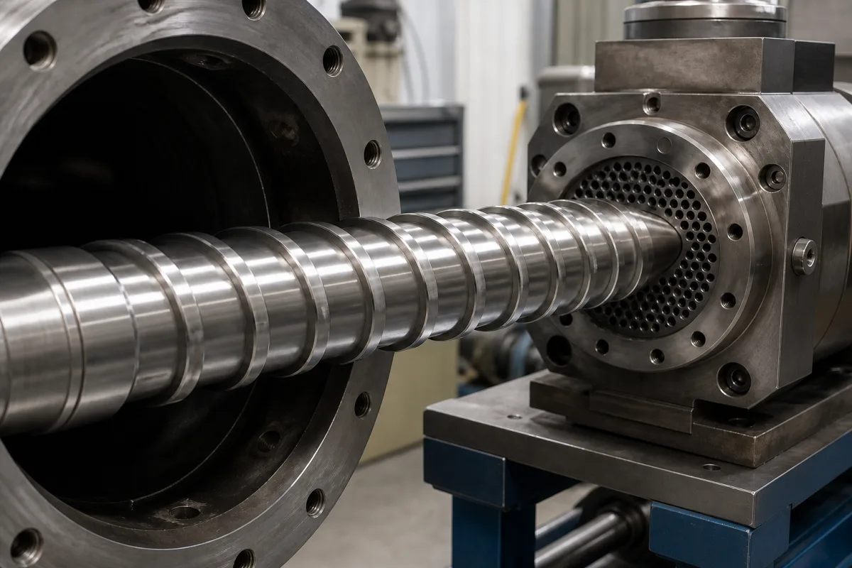
Representative product image. Confirm appearance and specifications with the manufacturer.

Product Specifications

Technical details and manufacturing context for Metering Section

Definition
The metering section is the downstream zone of an extrusion screw, following the melting/compression section. Its primary function is to homogenize the molten polymer, eliminate pressure fluctuations, and deliver a consistent volumetric flow rate to the die. It ensures uniform product dimensions and quality by maintaining steady pressure and temperature.

In extrusion screw design, the metering section is critical for achieving consistent output. It features a constant, shallow flight depth that creates shear and backpressure, further homogenizing the melt and removing any remaining solid particles. The geometry is designed to generate the pressure required to force the material through the die, ensuring predictable pumping and pressure generation.

Typical parameters for this component include screw diameter (20–150 mm), metering section length (4–6 D), channel depth (2–8 mm), flight width (0.08–0.12 D), radial clearance (0.1–0.4 mm), surface roughness (Ra 0.2–0.8 µm), hardness (56–62 HRC), operating temperature (180–400 °C), operating pressure (10–40 MPa), screw speed (20–120 rpm), throughput (5–500 kg/h), and weight (5–200 kg). Material grades such as 38CrMoAlA (per GB/T 3077) are referenced for wear resistance.

When selecting or verifying a metering section, confirm model-specific values with the legal manufacturer or supplier. The listed ranges are directory references and must be validated for the actual application. Standards, if any, serve as procurement references, not proof of certification or compliance.

Maintenance signals include increased pressure fluctuations, reduced output, or visible wear on flight surfaces. Failure boundaries may involve excessive wear to leakage flow, or thermal degradation due to high shear. Proper installation and alignment with the screw and barrel are essential for performance.
Working Principle
The metering section features a constant, shallow flight depth. As the screw rotates, the molten material is dragged forward by the screw flights. The shallow channel creates shear and backpressure, which further homogenizes the melt, removes any remaining solid particles, and generates the pressure required to force the material through the die. The constant geometry allows for predictable pumping and pressure generation.
Common Materials
Tool Steel, Nitrided Steel, Bimetallic Alloys, Stainless Steel
Technical Parameters
ParameterTypical rangeNotes & selection driver
Screw Diameter20–150 mmDetermines throughput and machine size
Metering Section Length4–6 DExpressed in screw diameters; affects pressure stability
Channel Depth2–8 mmShallower depth increases shear and pressure
Flight Width0.08–0.12 DAffects melt conveying and leakage flow
Radial Clearance0.1–0.4 mmTight clearance improves melt quality but risks wear
Surface RoughnessRa 0.2–0.8 µmSmooth finish prevents material adhesion
Hardness56–62 HRCWear resistance for abrasive compounds
Operating Temperature180–400 °CDepends on polymer melt temperature
Operating Pressure10–40 MPaHigher pressure ensures uniform die flow
Screw Speed20–120 rpmAffects residence time and shear rate
Throughput5–500 kg/hMatches extruder size and application
Material Grade38CrMoAlANitriding steel for wear resistanceGB/T 3077
Weight5–200 kgDepends on screw diameter and length

Ranges are indicative industry figures for RFQ preparation, not a supplier commitment. Confirm every value and standard with the legal manufacturer before ordering.

Components / BOM
  • Flight Part
    The helical ridge that conveys, shears, and pressurizes the material.
    Material: Tool Steel
  • Root Part
    The central shaft of the screw; the surface between flights where channel depth is measured.
    Material: Tool Steel
  • Flight Land Part
    The outer surface/edge of the flight that runs close to the barrel wall, providing sealing and shear.
    Material: Wear-Resistant Alloy

Applied To / Applications

This component is essential for the following industrial systems and equipment:

Industrial Ecosystem & Supply Chain Structure

Complementary Systems
Downstream Applications
Specialized Tooling

Application Fit & Sizing Matrix

Operational Limits
pressure: Up to 70 MPa (10,000 psi) typical, 100 MPa (14,500 psi) maximum
flow rate: 10-10,000 kg/hr (screw diameter dependent)
temperature: 150-350°C (depending on polymer type)
slurry concentration: Not applicable - designed for molten polymers, not slurries
Media Compatibility
✓ Polyethylene (LDPE/HDPE) ✓ Polypropylene (PP) ✓ Polyvinyl Chloride (PVC)
Unsuitable: Abrasive-filled compounds (e.g., glass fiber reinforced polymers above 30% filler content)
Sizing Data Required
  • Required output rate (kg/hr)
  • Polymer viscosity at processing temperature
  • Screw diameter and L/D ratio

Reliability & Engineering Risk Analysis

Failure Mode & Root Cause
Flow Measurement Drift
Cause: Accumulation of particulate matter or scaling on internal components (orifice plates, turbine blades, ultrasonic transducers), leading to inaccurate flow readings and calibration errors.
Seal or Gasket Failure
Cause: Chemical degradation, thermal cycling, or mechanical fatigue of sealing elements, resulting in leaks, pressure loss, and potential process fluid contamination or environmental release.
Maintenance Indicators
  • Unexplained fluctuations or deviations in flow readings compared to other process indicators (e.g., pump discharge pressure, tank levels).
  • Visible leaks, weeping, or residue buildup around flanges, fittings, or sensor housings, often accompanied by audible hissing or dripping.
Engineering Tips
  • Implement routine inline verification or calibration against a master meter or known volumetric standard to detect and correct drift early, especially after process upsets or changes in fluid composition.
  • Use compatible, high-quality sealing materials rated for the specific process fluid, temperature, and pressure, and follow proper torque procedures during installation to prevent over-compression or under-compression.

Indicative industry ranges for design and RFQ preparation. Confirm the exact figures and applicable standard with the manufacturer before specifying.

Compliance & Manufacturing Standards

Applicable Standards
ISO 5167: Flow measurement by means of pressure differential devices ANSI B16.5: Pipe Flanges and Flanged Fittings CE Marking: Pressure Equipment Directive 2014/68/EU

Quoted from the published standard.

Manufacturing Precision
  • Bore diameter: +/-0.05mm
  • Surface flatness: 0.08mm per 100mm
Quality Inspection
  • Pressure Leak Test
  • Dimensional Verification with CMM

Manufacturers of Metering Section

Manufacturer profiles associated with Metering Section.

Sourcing Metering Section from China?
Tell us your specification and target quantity — we will match it against manufacturer records and come back with the factories that fit.
Request manufacturers We manufacture this

Manufacturer listings support early research and capability understanding. They are not certification, ranking, or transaction guarantees.

Technical documentation
Request current drawings, revision history, and a signed specification sheet.
Manufacturing capability
Verify equipment lists, process limits, capacity, and representative production evidence.
Inspection readiness
Confirm test methods, calibrated equipment, sampling plans, and traceable reports.
Supplier transparency
Check the legal entity, factory address, ownership, certifications, and direct contacts.

CNFX does not score or rank suppliers. Buyers must verify all claims and documents with the legal manufacturer before ordering.

Supply Chain Compatible Machinery & Devices

Multi-Layer Co-Extruded Barrier Film

This product is a high-performance plastic film manufactured using co-extrusion technology to combine multiple polymer layers into a single sheet.

Explore Specs →
High-Precision Silicone Gasket

A precision-engineered sealing component manufactured from liquid silicone rubber (LSR) via injection molding.

Explore Specs →
Silicone Rubber

A synthetic elastomer composed of silicone polymers with exceptional temperature resistance, flexibility, and chemical stability.

Explore Specs →
Non-post Cured

A rubber or plastic processing machine that produces cured products without requiring a separate post-curing stage.

Explore Specs →

Frequently Asked Questions

What is the primary function of the metering section?

The metering section homogenizes the molten polymer, eliminates pressure fluctuations, and delivers a consistent volumetric flow rate to the die, ensuring uniform product dimensions and quality.

What are typical parameters for a metering section?

Typical parameters include screw diameter 20–150 mm, metering section length 4–6 D, channel depth 2–8 mm, flight width 0.08–0.12 D, radial clearance 0.1–0.4 mm, surface roughness Ra 0.2–0.8 µm, hardness 56–62 HRC, operating temperature 180–400 °C, operating pressure 10–40 MPa, screw speed 20–120 rpm, throughput 5–500 kg/h, and weight 5–200 kg. These are reference ranges; confirm with the manufacturer.

How does the metering section affect product quality?

By maintaining steady pressure and temperature, the metering section ensures uniform melt delivery, which directly impacts product dimensions and surface finish. Shallow channel depth increases shear, improving homogenization but also raising temperature.

What maintenance signals indicate a problem with the metering section?

Signs include increased pressure fluctuations, reduced output, or visible wear on flight surfaces. Excessive wear can lead to leakage flow, while high shear may cause thermal degradation. Regular inspection and measurement of critical dimensions are recommended.

Data Basis

Editorial classification, named public sources where available, and source-reviewed manufacturer records.

Preliminary Technical Classification
This page supports structured research, RFQ preparation, and supplier evaluation. It does not replace buyer-led supplier qualification, standards review, or technical approval.
Buyer enquiry

Request manufacturing insight for Metering Section

Ask for use case, specification boundaries, supplier type, and RFQ preparation information for this product.

Where it goes
Straight to the CNFX editorial desk, and to the manufacturer if this product is linked to a claimed profile. Nothing is broadcast to a supplier list.
Your details stay here
We do not sell or rent enquiry data, and we do not add you to a mailing list. Used only to answer this request.
No commission, no middleman
CNFX is a directory. We take no cut of any order and never negotiate on a supplier's behalf.
What we don't claim
A listing is not an endorsement. Qualify every supplier and verify every figure yourself before ordering.

Your business information is used only to process this request.

Thank you! Your message has been sent. We'll respond within 1–3 business days.
Sorry, we couldn't send your message. Please try again, or email us at contact@cnfx.com.

Need to Manufacture Metering Section?

Compare manufacturer profiles with relevant product and process capability.

Previous Product
Spray Manipulator
Last Product
Get QuotesChat