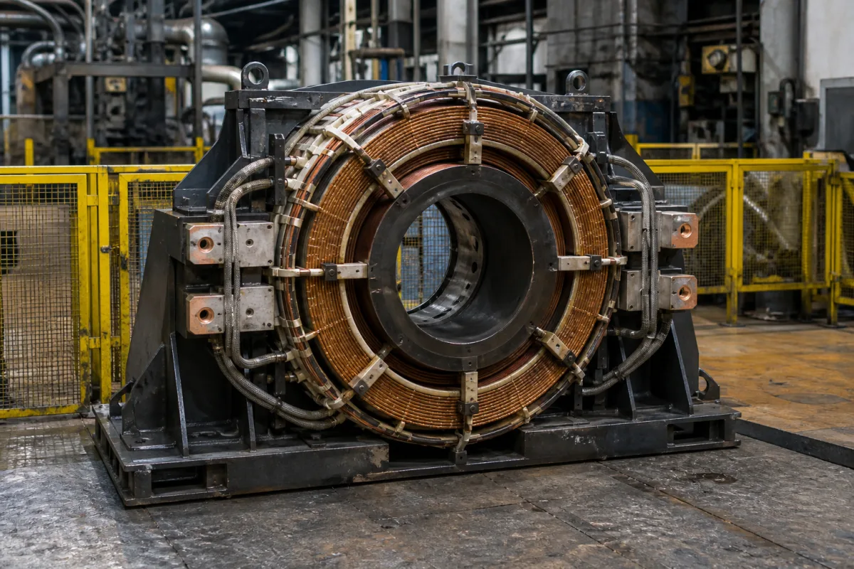
Mould electromagnetic stirrer (M-EMS) coil assembly for billet and round bloom casting
Mould electromagnetic stirrer (M-EMS) coils · three-phase rotating field for billet and round bloom moulds, 1–8 Hz, inside or outside the mould
A mould electromagnetic stirrer (M-EMS) coil assembly is a ring of copper coils on a laminated iron core, fed with low-frequency three-phase current, that fits around a billet or bloom mould and sets the molten steel rotating horizontally inside it. Ask three things first: whether the stirrer is installed inside the mould water jacket or outside the mould, what frequency and current range the power supply delivers, and which section sizes it must stir through the mould copper.
Rotating-field electromagnetic stirrer coil assemblies fitted at the mould of billet, bloom and round bloom continuous casters, with their cores, windings and cooling. Static-field electromagnetic brakes for slab moulds are covered on the Industrial-grade continuous casting mold electromagnetic brake system page. Strand and final stirrers, and small solenoid and actuator coils, are outside this page.
CNFX editorial research · Sources checked October 12, 2026 · 3 sources
Kishore Windwell, an EMS coil maker, classes stirrers by position along the strand as mould (M-EMS), strand (S-EMS) and final (F-EMS) stirrers, and lists four mould arrangements: inside the mould using mould water (2–8 Hz), inside the mould water jacket with a separate clean-water circuit (2–8 Hz), outside the mould with separate cooling water, which makes copper tube changes simple and suits a wide range of sections (2–5 Hz), and an inner-cooling type that can go inside or outside the mould (1–6 Hz). [1]
The same maker describes the inside-mould type on mould water as convenient and low in cost, the clean-water version as compact and long-lived, and the inner-cooling type as giving an even field but with higher magnetic leakage, strict cooling-water quality requirements and higher operating cost. [1]
Section size and mould copper both matter. In a round-bloom study with a stirrer of 1,010 mm inner diameter, 1,510 mm outer diameter and 300 mm height, at 280 A and 2 Hz, reducing the section from Φ650 to Φ550 mm moved the strand surface farther from the coil while the copper tube stayed 29 mm thick, and the maximum electromagnetic force fell from 440.0 to 227.4 N/m³; at Φ450 and Φ350 mm, with 25 mm copper, the force rose again. [3] With the stirrer and a smaller strand off-centre (eccentric stirring), the outer-arc side received more force than the inner-arc side, by 143.1 N/m³ at Φ350 mm and 6.6 N/m³ at Φ550 mm. [3] Editorial note: give the supplier every section and copper thickness you will cast through the same stirrer, and ask for the force at each.
Give the supplier the caster type and radius, every section size, mould copper thickness, mounting position (inside water jacket or outside the mould), available cooling water and its quality, power supply, required frequency and current range, stirring mode (continuous or alternating), and the steel grades and quality targets.
02
Set the current and frequency range
In a 200 mm × 200 mm square billet study with a stirrer of 12 coil packages on a toroidal core, varying the current from 0 to 500 A showed the lowest carbon segregation at 300 A, and segregation rose with frequency between 3 and 5 Hz; 3 Hz with 300 A was the best setting found, and the maximum tangential steel velocity was 0.19, 0.31 and 0.38 m/s at 100, 300 and 500 A. [2]
In the round-bloom study, three pairs of windings in twelve coil rows carried three-phase current 120° apart; the maximum electromagnetic force rose from 151 N/m³ at 180 A to 367 N/m³ at 280 A and 2,163 N/m³ at 680 A, and measured flux density at the centre fell as frequency rose while measured torque peaked near 2 Hz. [3] Editorial calculation: from 280 A to 680 A the current rises 2.43 times and the force 5.89 times, close to the square of the current ratio (5.90).
Editorial note: because flux density and stirring torque move in opposite directions over part of the frequency range, ask the supplier for measured torque (or force) against frequency at your section, not flux density alone.
03
Four round-bloom sections served by one stirrer
The round-bloom study modelled one stirrer (1,010 mm bore, 300 mm high) on a caster with a 660 mm effective mould length casting four sections, each with its own copper tube, speed and mould water. [3]
The authors attribute the dip at Φ550 mm to the combined effect of the thicker copper tube's magnetic shielding and the field's decay in air, and conclude that, of the four, the Φ650 mm section has the highest efficiency in converting electromagnetic energy into kinetic energy. [3] Editorial note: if a stirrer must serve more than one section, ask the supplier for the force at each one with its own copper thickness, not only at the design section.
Explore company information and manufacturing capabilities, then discuss the scope of your project with a relevant supplier.
Share this page
Compiled and source-reviewed by the CNFX editorial team.
Each manufacturer above links to the page on that company's own website where the product is listed, with the date we checked it. How we source and review
· Page last updated 13 October 2026
Buyer questions
What frequency does a mould electromagnetic stirrer run at?
One coil maker lists 2–8 Hz for stirrers inside the mould and 2–5 Hz outside it, and 1–6 Hz for an inner-cooling type. [1]
What current suits a 200 × 200 mm billet?
In one study, 3 Hz and 300 A gave the best control of carbon segregation over a 0–500 A range. [2]
Is an M-EMS the same as an electromagnetic brake?
No; the M-EMS coils carry three-phase current that rotates the steel, while brakes apply a static field to slab moulds. [3]
Sources and what still needs a direct check
Sources checked 2026-10-12. Mounting types and frequency ranges come from an EMS coil maker's product page; the current and field data from two open-access studies in Materials (MDPI), one with an EMS maker's research institute among the authors. Study values apply to the casters modelled; confirm settings for your caster with the supplier.