Editorial Technical Reference

Hydraulic Actuator

This page explains how Hydraulic Actuator is classified within Basic Metal Manufacturing. Technical values and manufacturer relationships are research references; confirm the current specification and supplier evidence for each order.

Technical Definition & Core Assembly

A hydraulic-powered mechanical device that converts fluid pressure into linear or rotary motion to precisely control the oscillation of continuous casting molds.

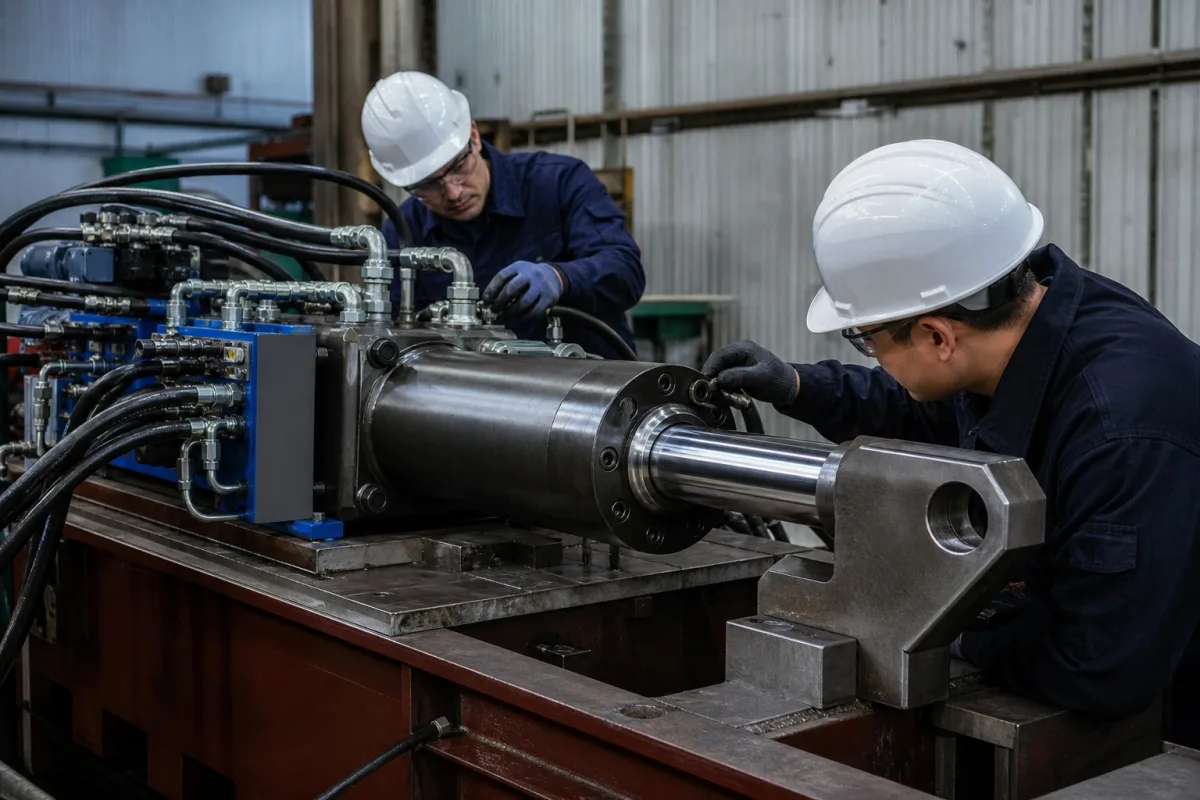
Representative product image. Confirm appearance and specifications with the manufacturer.

Product Specifications

Technical details and manufacturing context for Hydraulic Actuator

Definition
A hydraulic actuator is a critical component within the Continuous Casting Mold Oscillator system that provides controlled mechanical movement to the mold assembly. It uses hydraulic fluid pressure to generate precise linear or oscillatory motion, enabling the mold to oscillate at specific frequencies and amplitudes during the continuous casting process to prevent sticking and ensure uniform solidification of the steel strand. The actuator is designed for the demanding environment of basic metal manufacturing, where reliability and precision are paramount. It is typically constructed with a high-strength steel body, chromium-plated piston rods for corrosion resistance, and bronze or polymer seals to ensure leak-free operation. The hydraulic fluid used must be compatible with the system and operating conditions. Key parameters include an operating pressure range of 1.0–1.6 MPa, a stroke length of 50–500 mm, thrust force of 5–100 kN, positioning accuracy of ±0.05 mm, response time of ≤50 ms, operating temperature of -20 to 80 °C, ingress protection rating of IP65–IP67 (per IEC 60529), supply voltage of 24 V DC ±10%, material QT500-7 (per GB/T 1348), and weight of 15–60 kg. These values are reference ranges and must be verified for the specific model and application. The actuator is controlled by a closed-loop system that regulates fluid flow and pressure based on casting parameters. It is essential to confirm model-specific values and standards with the legal manufacturer or supplier before procurement. The actuator's performance directly impacts the quality of the cast product, making proper selection and maintenance critical.
Working Principle
Hydraulic fluid under pressure is directed into the actuator cylinder, forcing a piston to move linearly. This motion is transmitted to the mold assembly through mechanical linkages. The direction, speed, and force of movement are controlled by hydraulic valves and a control system that regulates fluid flow and pressure based on casting parameters. The closed-loop control ensures precise positioning and oscillation frequency, which are essential for preventing mold sticking and ensuring uniform solidification. The actuator's response time and accuracy are critical for maintaining the desired mold oscillation pattern.
Common Materials
High-strength steel, Chromium-plated piston rods, Bronze or polymer seals, Hydraulic fluid
Technical Parameters
ParameterTypical rangeNotes & selection driver
Stroke Length50–500 mmCustom lengths available
Thrust Force5–100 kNDepends on pressure and piston area
Positioning Accuracy±0.05 mmClosed-loop control required
Response Time≤50 msFrom signal to full stroke
Operating Temperature-20–80 °CSeals may limit range
Ingress ProtectionIP65–IP67Higher for washdown environmentsIEC 60529
Supply Voltage24 ±10% V DCFor integrated sensors/valves
MaterialQT500-7Ductile iron bodyGB/T 1348
Weight15–60 kgDepends on stroke and options

Ranges are indicative industry figures for RFQ preparation, not a supplier commitment. Confirm every value and standard with the legal manufacturer before ordering.

Components / BOM
  • Cylinder Barrel Part
    Contains hydraulic fluid and guides piston movement
    Material: High-strength steel
  • Piston Part
    Converts hydraulic pressure into linear force
    Material: Hardened steel with chrome plating
  • Piston Rod Part
    Transmits force from piston to external load
    Material: Chrome-plated steel
  • Seals Part
    Prevent hydraulic fluid leakage and contamination
    Material: Polyurethane or nitrile rubber
  • Mounting Brackets Part
    Secure actuator to mold oscillator frame
    Material: Structural steel

Applied To / Applications

This component is essential for the following industrial systems and equipment:

Industrial Ecosystem & Supply Chain Structure

Complementary Systems
Downstream Applications
Specialized Tooling

Application Fit & Sizing Matrix

Operational Limits
pressure: Up to 210 bar (3000 psi)
flow rate: 10-100 L/min
temperature: -20°C to +80°C
slurry concentration: Up to 5% solids by weight
Media Compatibility
✓ Hydraulic oil (ISO VG 32-68) ✓ Water-glycol fluids ✓ Phosphate ester fluids
Unsuitable: High-chloride aqueous environments (causes corrosion)
Sizing Data Required
  • Required force/thrust (kN)
  • Stroke length (mm)
  • Operating cycle frequency (cycles/min)

Reliability & Engineering Risk Analysis

Failure Mode & Root Cause
Seal degradation
Cause: Contamination ingress, chemical incompatibility, or excessive temperature causing hardening, cracking, or extrusion of seals, leading to internal and external leakage.
Piston rod scoring or corrosion
Cause: Inadequate rod wiper seal allowing abrasive contaminants to enter, improper rod surface finish, exposure to corrosive environments, or lack of protective coatings leading to seal damage and fluid leakage.
Maintenance Indicators
  • Audible hissing or knocking sounds during operation indicating internal leakage, cavitation, or air entrapment.
  • Visible external hydraulic fluid leakage around rod seals, cylinder body, or ports, often accompanied by reduced actuator speed or force output.
Engineering Tips
  • Implement strict contamination control: Use high-quality filtration (e.g., 10-micron or finer), maintain proper fluid cleanliness per ISO 4406 standards, and ensure breathers and rod wipers are functional to prevent abrasive wear.
  • Establish regular preventive maintenance: Perform periodic seal inspections and replacements based on operating hours, monitor fluid temperature and quality, and verify proper rod alignment and mounting to prevent side-loading and premature wear.

Indicative industry ranges for design and RFQ preparation. Confirm the exact figures and applicable standard with the manufacturer before specifying.

Compliance & Manufacturing Standards

Applicable Standards
ISO 6020-2: Hydraulic fluid power - Mounting dimensions for single rod cylinders, 16 MPa series ANSI/NFPA T3.6.7: Fluid power systems and components - Cylinders - Method for verifying the fatigue and establishing the burst pressure ratings DIN ISO 3320: Fluid power systems and components - Cylinder bores and piston rod diameters - Metric series

Quoted from the published standard.

Manufacturing Precision
  • Bore diameter: +/-0.02 mm
  • Piston rod straightness: 0.1 mm per meter length
Quality Inspection
  • Pressure test: Hydrostatic testing to 1.5 times maximum working pressure
  • Leakage test: Internal and external leakage verification under maximum operating pressure

Manufacturers of Hydraulic Actuator

2 companies list this product among what they make. Company figures are quoted from each company's own website; every card states where the relationship came from.

ChengZhou Technology
Guangdong, CN
Listed on the company's own website · profile compiled by CNFX from public sources
Zhejiang Bigtork Valve Automation Co., Ltd.
Zhejiang, CN
Listed on the company's own website · profile compiled by CNFX from public sources

Manufacturer listings support early research and capability understanding. They are not certification, ranking, or transaction guarantees.

Technical documentation
Request current drawings, revision history, and a signed specification sheet.
Manufacturing capability
Verify equipment lists, process limits, capacity, and representative production evidence.
Inspection readiness
Confirm test methods, calibrated equipment, sampling plans, and traceable reports.
Supplier transparency
Check the legal entity, factory address, ownership, certifications, and direct contacts.

CNFX does not score or rank suppliers. Buyers must verify all claims and documents with the legal manufacturer before ordering.

Supply Chain Compatible Machinery & Devices

Vacuum Induction Melting Furnace

Industrial furnace for melting metals under vacuum using electromagnetic induction

Explore Specs →
Electroslag Remelting Furnace

An industrial furnace used in basic metal manufacturing for secondary refining of alloys through the electroslag remelting (ESR) process.

Explore Specs →
Molten Metal Temperature Measurement System

Automated system for continuous temperature monitoring of molten metals during processing.

Explore Specs →
Molten Metal Degassing System

The Molten Metal Degassing System is an industrial system used in basic metal manufacturing to remove dissolved hydrogen, oxygen, and nitrogen from molten aluminum, steel, and other non-ferrous metals.

Explore Specs →

Frequently Asked Questions

What is the operating pressure range for this hydraulic actuator?

The reference operating pressure range is 1.0–1.6 MPa. However, the actual required pressure depends on the specific application and must be verified with the manufacturer.

What is the stroke length and thrust force?

The stroke length ranges from 50 to 500 mm, and the thrust force ranges from 5 to 100 kN. These are reference values; custom lengths may be available, and actual performance depends on pressure and piston area.

What is the positioning accuracy and response time?

The positioning accuracy is ±0.05 mm, and the response time is ≤50 ms from signal to full stroke. Closed-loop control is required to achieve these specifications.

What are the environmental and electrical requirements?

The operating temperature range is -20 to 80 °C, and the ingress protection rating is IP65–IP67 per IEC 60529. The supply voltage is 24 V DC ±10%. Seals may limit the temperature range, and higher protection may be needed for washdown environments.

Data Basis

Editorial classification, named public sources where available, and source-reviewed manufacturer records.

Preliminary Technical Classification
This page supports structured research, RFQ preparation, and supplier evaluation. It does not replace buyer-led supplier qualification, standards review, or technical approval.
Buyer enquiry

Request manufacturing insight for Hydraulic Actuator

Ask for use case, specification boundaries, supplier type, and RFQ preparation information for this product.

Where it goes
Straight to the CNFX editorial desk, and to the manufacturer if this product is linked to a claimed profile. Nothing is broadcast to a supplier list.
Your details stay here
We do not sell or rent enquiry data, and we do not add you to a mailing list. Used only to answer this request.
No commission, no middleman
CNFX is a directory. We take no cut of any order and never negotiate on a supplier's behalf.
What we don't claim
A listing is not an endorsement. Qualify every supplier and verify every figure yourself before ordering.

Your business information is used only to process this request.

Thank you! Your message has been sent. We'll respond within 1–3 business days.
Sorry, we couldn't send your message. Please try again, or email us at contact@cnfx.com.

Need to Manufacture Hydraulic Actuator?

Compare manufacturer profiles with relevant product and process capability.

Previous Product
Hot Metal Torpedo Car
Next Product
Hydraulic Forging Press
Get QuotesChat