Editorial Technical Reference

Pressure Testing Unit

This page explains how Pressure Testing Unit is classified within Beverage Manufacturing. Technical values and manufacturer relationships are research references; confirm the current specification and supplier evidence for each order.

Technical Definition & Core Assembly

A specialized component within an automated kegging and barrel filling system that verifies the integrity and pressure-holding capability of containers before filling.
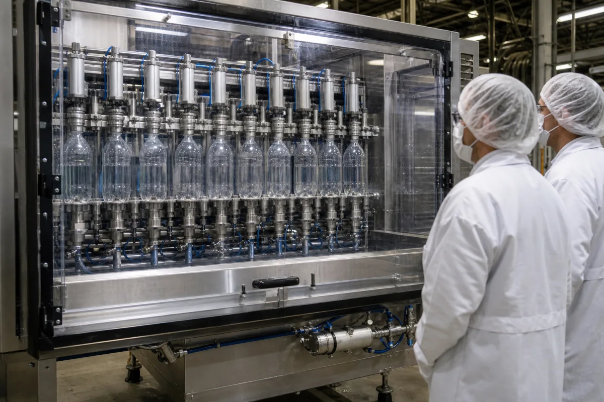
Representative product image. Confirm appearance and specifications with the manufacturer.

Product Specifications

Technical details and manufacturing context for Pressure Testing Unit

Definition
The Pressure Testing Unit is a critical safety and quality control component within an Automated Kegging and Barrel Filling System. Its primary role is to perform automated pressure tests on empty kegs and barrels to ensure they are free from leaks and can safely hold the intended pressure of the beverage (e.g., beer, cider, kombucha) during carbonation, storage, and transport. It identifies defective containers before the filling process, preventing product loss, contamination, and potential safety hazards. The unit typically clamps or seals onto the container's opening, pressurizes it with an inert gas (like air or nitrogen) to a predetermined test pressure, holds the pressure for a set duration, and monitors for any pressure drop using precision sensors. A significant pressure drop indicates a leak, and the container is automatically rejected from the production line. The unit is designed for integration into existing filling lines, with a compact footprint (800×600×1200 mm) and a weight ranging from 80 to 150 kg depending on the number of test stations (1 to 4). It operates within a temperature range of 5–45 °C and requires a stable 24 V DC supply (±10%). Power consumption varies from 0.5 to 1.5 kW. The wetted parts are made of stainless steel 316L (ASTM A240) to resist corrosion from beverage contact, while other components use AISI 304/316 stainless steel, food-grade elastomers, and anodized aluminum. The unit offers an ingress protection rating of IP54–IP65 (IEC 60529) to guard against dust and water jets. Key parameters include an operating pressure of 1.0–1.6 MPa, a test pressure range of 0.5–2.5 MPa, pressure accuracy of ±0.01 MPa, and a cycle time of 15–60 seconds. These values are reference ranges; actual specifications must be confirmed with the manufacturer for the specific model and application. Always verify model-specific values and standards with the legal manufacturer or supplier before procurement.
Working Principle
The unit clamps or seals onto the container's opening. It then pressurizes the container with an inert gas (like air or nitrogen) to a predetermined test pressure, holds the pressure for a set duration, and monitors for any pressure drop using precision sensors. A significant pressure drop indicates a leak, and the container is automatically rejected from the production line. The test pressure range is adjustable from 0.5 to 2.5 MPa, with an accuracy of ±0.01 MPa. The cycle time, including pressurization, hold, and release, ranges from 15 to 60 seconds. Multiple test stations (1–4) allow parallel testing to increase throughput.
Common Materials
Stainless Steel (AISI 304/316), Food-grade elastomers (seals, gaskets), Anodized Aluminum
Technical Parameters
ParameterTypical rangeNotes & selection driver
Test Pressure Range0.5–2.5 MPaAdjustable for different container ratings
Pressure Accuracy±0.01 MPaEnsures reliable leak detection
Cycle Time15–60 sIncludes pressurization, hold, and release
Number of Test Stations1–4 stationsParallel testing increases throughput
Supply Voltage24 ±10% V DCStable voltage required for sensors
Power Consumption0.5–1.5 kWDepends on compressor and electronics
Operating Temperature5–45 °COutside range may affect sensor accuracy
Ingress ProtectionIP54–IP65Protects against dust and water jetsIEC 60529
Material (wetted parts)316LCorrosion-resistant for beverage contactASTM A240
Weight80–150 kgVaries with number of stations
Dimensions (L×W×H)800×600×1200 mmCompact footprint for line integration

Ranges are indicative industry figures for RFQ preparation, not a supplier commitment. Confirm every value and standard with the legal manufacturer before ordering.

Components / BOM
  • Test Head / Clamping Mechanism
    Seals against the container opening (e.g., keg spear) to create a pressure-tight connection.
    Material: Stainless Steel, Food-grade Rubber
  • Pressure Sensor/Transducer
    Precisely measures the internal pressure of the container during the test cycle.
    Material: Stainless Steel, Ceramic
  • Solenoid Valve Bank
    Controls the flow of pressurization gas (fill) and venting gas (exhaust) to and from the container.
    Material: Brass, Stainless Steel
  • Programmable Logic Controller (PLC) Interface
    Receives commands from and sends test results (Pass/Fail) to the main system controller.
    Material: Plastic, Electronic Components
  • Reject Mechanism
    Takes the leaking container off the line once the pressure test fails it.

Industrial Ecosystem & Supply Chain Structure

Complementary Systems
Downstream Applications
Specialized Tooling

Application Fit & Sizing Matrix

Operational Limits
pressure: 0 to 10 bar (test range), 15 bar (maximum system pressure)
flow rate: Up to 60 L/min (air/nitrogen), 20 L/min (liquid)
cycle time: 15-90 seconds per container (depending on volume and test pressure)
temperature: 5°C to 40°C (operating), -10°C to 60°C (storage)
slurry concentration: Not applicable (clean gas/liquid media only)
Media Compatibility
✓ Food-grade CO2/N2 gas mixtures ✓ Deionized water/CIP cleaning solutions ✓ Stainless steel/PTFE-lined containers
Unsuitable: Abrasive slurries or corrosive chemical media
Sizing Data Required
  • Maximum container volume (L)
  • Required test pressure (bar)
  • Production throughput (containers/hour)

Reliability & Engineering Risk Analysis

Failure Mode & Root Cause
Seal/gasket degradation
Cause: Chemical incompatibility with test media, thermal cycling, or excessive pressure causing extrusion and loss of sealing integrity.
Pressure transducer/sensor drift or failure
Cause: Overpressure events, moisture ingress, electrical noise, or mechanical vibration leading to calibration loss or component damage.
Maintenance Indicators
  • Audible hissing or whistling indicating a leak in the pressure circuit or fittings.
  • Visual signs of fluid weeping, corrosion, or discoloration around seals, valves, or pressure connections.
Engineering Tips
  • Implement a rigorous calibration and verification schedule for pressure sensors and gauges, using traceable standards and documenting drift trends.
  • Use compatible, clean, and filtered test media, and perform regular flushing to prevent contamination buildup that accelerates wear.

Indicative industry ranges for design and RFQ preparation. Confirm the exact figures and applicable standard with the manufacturer before specifying.

Compliance & Manufacturing Standards

Applicable Standards
ISO 5167-1:2022 (Measurement of fluid flow by means of pressure differential devices) ASME B40.100-2022 (Pressure Gauges and Gauge Attachments) DIN EN 837-1:2018 (Pressure gauges - Part 1: Bourdon tube pressure gauges)

Quoted from the published standard.

Manufacturing Precision
  • Pressure measurement accuracy: +/-0.25% of full scale
  • Leak rate: ≤ 1×10⁻⁹ mbar·L/s at test pressure
Quality Inspection
  • Hydrostatic pressure test (1.5× maximum working pressure for 30 minutes)
  • Calibration verification against NIST-traceable reference standards

Manufacturers of Pressure Testing Unit

Manufacturer profiles associated with Pressure Testing Unit.

Sourcing Pressure Testing Unit from China?
Tell us your specification and target quantity — we will match it against manufacturer records and come back with the factories that fit.
Request manufacturers We manufacture this

Manufacturer listings support early research and capability understanding. They are not certification, ranking, or transaction guarantees.

Technical documentation
Request current drawings, revision history, and a signed specification sheet.
Manufacturing capability
Verify equipment lists, process limits, capacity, and representative production evidence.
Inspection readiness
Confirm test methods, calibrated equipment, sampling plans, and traceable reports.
Supplier transparency
Check the legal entity, factory address, ownership, certifications, and direct contacts.

CNFX does not score or rank suppliers. Buyers must verify all claims and documents with the legal manufacturer before ordering.

Supply Chain Compatible Machinery & Devices

Automated Beverage Container Integrity Testing System

Automated system for non-destructive testing of beverage container seals and structural integrity.

Explore Specs →
Automated Beverage Container Pressure Testing System

Automated system for testing beverage container pressure resistance and seal integrity.

Explore Specs →
Automated Beverage Container Leak Detection System

The Automated Beverage Container Leak Detection System is an industrial device designed for integration into bottling or canning lines.

Explore Specs →
Automated Beverage Container Depalletizing Machine

Industrial machine that automatically removes beverage containers from pallets for production line feeding

Explore Specs →

Frequently Asked Questions

What is the purpose of the Pressure Testing Unit?

It verifies that empty kegs and barrels are free from leaks and can safely hold the intended beverage pressure before filling, preventing product loss and safety hazards.

What test pressures can the unit apply?

The test pressure range is adjustable from 0.5 to 2.5 MPa, with an accuracy of ±0.01 MPa. The operating pressure range is 1.0–1.6 MPa.

How does the unit detect leaks?

It pressurizes the container with inert gas, holds the pressure for a set duration, and monitors for pressure drop using precision sensors. A significant drop indicates a leak, and the container is rejected.

What are the installation requirements?

The unit requires a stable 24 V DC supply (±10%), operates in 5–45 °C, and has a compact footprint of 800×600×1200 mm. Power consumption is 0.5–1.5 kW. Verify specific requirements with the manufacturer.

Data Basis

Editorial classification, named public sources where available, and source-reviewed manufacturer records.

Preliminary Technical Classification
This page supports structured research, RFQ preparation, and supplier evaluation. It does not replace buyer-led supplier qualification, standards review, or technical approval.
Buyer enquiry

Request manufacturing insight for Pressure Testing Unit

Ask for use case, specification boundaries, supplier type, and RFQ preparation information for this product.

Where it goes
Straight to the CNFX editorial desk, and to the manufacturer if this product is linked to a claimed profile. Nothing is broadcast to a supplier list.
Your details stay here
We do not sell or rent enquiry data, and we do not add you to a mailing list. Used only to answer this request.
No commission, no middleman
CNFX is a directory. We take no cut of any order and never negotiate on a supplier's behalf.
What we don't claim
A listing is not an endorsement. Qualify every supplier and verify every figure yourself before ordering.

Your business information is used only to process this request.

Thank you! Your message has been sent. We'll respond within 1–3 business days.
Sorry, we couldn't send your message. Please try again, or email us at contact@cnfx.com.

Need to Manufacture Pressure Testing Unit?

Compare manufacturer profiles with relevant product and process capability.

Previous Product
Vacuum Gripper End-Effector
Last Product
Get QuotesChat