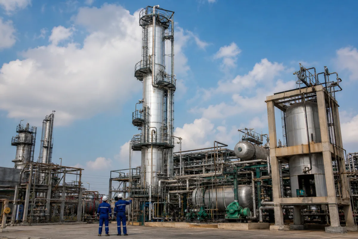
Crude oil fractionating column: the atmospheric crude distillation tower with side draws, side strippers and pumparounds
The atmospheric crude tower at the head of a refinery · crude fed near the bottom at 650–700 °F, products drawn off the side and finished in side strippers, pumparounds that shrink the tower from 5.18 m to 4.27 m, and an energy use of about 109,000 Btu per barrel
The US Department of Energy describes refinery operations as starting at the atmospheric crude distillation unit, one tall column. Desalted, preheated crude is heated in a fired heater and flashed into the lower part of the atmospheric tower; residue leaves the bottom, gas and naphtha leave the top, and kerosene and gas oils are drawn off trays in between, then cleaned of light ends in small side strippers. Liquid is also pumped out of the tower, cooled against incoming crude and returned higher up: these pumparounds set the tower's diameter and much of the refinery's heat recovery.
Atmospheric crude oil fractionating towers in petroleum refineries (crude distillation units), with their flash zone, side draws, steam or reboiled side strippers, pumparound circuits and stripping steam. General trayed and packed distillation columns for chemical plants are covered on the Distillation column page; column trays and packing on the Distillation trays and packing (column internals) page; skid-mounted solvent recovery columns on the Skid-mounted chemical distillation system for solvent recovery and purification, Continuous solvent recovery and purification system and Solvent recovery unit pages. Vacuum towers are mentioned only where they take the atmospheric residue.
CNFX editorial research · Sources checked October 12, 2026 · 3 sources
From flash zone to side draws: how crude is split inside the atmospheric tower
OSHA's Technical Manual describes the atmospheric tower: desalted crude preheated by recovered heat passes through a direct-fired charge heater and enters the column just above the bottom, at slightly above atmospheric pressure and 650 to 700 °F; hotter would risk thermal cracking. All but the heaviest fractions flash to vapour, residue leaves the bottom, and lubricating oil, heating oil, kerosene, gasoline and uncondensed gases are drawn at successively higher points. OSHA gives the tower as a steel cylinder about 120 ft high with horizontal trays fitted with perforations and bubble caps. [1]
Editorial conversion: 650 to 700 °F is about 343 to 371 °C, and 120 ft is about 37 m. OSHA adds that the residue or topped crude goes on to vacuum towers, and that small steam strippers remove trace light products from heavier streams. [1]
A University of Pannonia (MOL department) model of an atmospheric tower makes the arrangement concrete: [2]
Model tower feature (Varga and Lóczi, 2016)
Value
Main column
32 theoretical stages with a partial condenser [2]
Feed
Desalted crude at up to 350 °C, entering stage 30 [2]
Pressure
2.0 bar at the top stage, 2.8 bar at the bottom; 0.8 bar average drop [2]
4 stages; fed from stage 9, vapour back to stage 8; reboiler at 227 °C [2]
Side stripper 2 (light gas oil)
4 stages; fed from stage 15, vapour back to stage 14 [2]
Product outlet temperatures (base case)
Top vapour 135 °C, kerosene 227 °C, light gas oil 252 °C, heavy gas oil 306 °C, residue 322 °C [2]
Give the column designer the crude assay or blend range, throughput, product cut points and the number of side draws and side strippers wanted, with steam or reboiler stripping for each.
02
Pumparounds: how taking heat out mid-tower shrinks the column from 5,180 to 4,270 mm
Varga and Lóczi compared the same tower with no pumparound, one, and two. A pumparound draws liquid from one stage, cools it and returns it to the stage above, taking heat out of the column at a higher temperature than the overhead condenser can. [2]
The authors note that the internal flows became more uniform with pumparounds, but that the trays of a pumparound section need special design for their high liquid loads, and that the kerosene stripper's reboiler duty rose (752 kW to 1,365 and 1,423 kW) because the kerosene draw tray ran cooler. [2]
Editorial calculation: going from 5,180 to 4,270 mm reduces the diameter by 17.6 % and the cross-sectional area by about 32 % (4,270² ÷ 5,180² ≈ 0.68); the external heating requirement falls by about 42 % (13,569 ÷ 23,256 ≈ 0.58).
Ask for the pumparound draw and return stages, duties and temperature drops, and the tray design in each pumparound section, since those sections set the tower diameter.
03
Energy: about 109,000 Btu per barrel, and where the savings are
The US Department of Energy's 2015 bandwidth study lists atmospheric crude distillation as the first and largest energy-consuming refinery process: 109,100 Btu per barrel on 5,540 million barrels a year in 2010, or 604 TBtu of onsite energy. [3]
DOE estimates that state-of-the-art practice would bring that to 522 TBtu, a saving of 82 TBtu a year; it names retrofitting the crude preheat train to reach the highest possible furnace inlet temperature as the main method, while noting that higher temperatures speed up asphaltene fouling, so an active exchanger cleaning programme may be needed. [3] Its list of opportunities for the crude unit includes process controls, high-temperature combined heat and power, pinch analysis, furnace controls, air preheating and progressive crude distillation. [3]
US refineries ran about 15 million barrels per stream day of crude distillation in 2010 against 17.6 million of capacity, with single refineries ranging from about 3,300 to 625,000 barrels per stream day. [3] Editorial calculation: 82 ÷ 604 ≈ 14 % of the atmospheric tower's energy; the pumparound results above, where crude leaves the preheat train 33 °C hotter, are one route to that furnace-inlet gain.
04
What to send for a crude oil fractionating column
Paste it into your enquiry below or into an email to a maker, then replace every bracket.
Feed: [crude assay or blend range; throughput bbl/day; desalter outlet temperature]
Products: [cut points; number of side draws; side strippers, steam or reboiled]
Tower: [stages or trays; flash zone conditions; top and bottom pressure]
Heat recovery: [pumparounds; draw and return stages; duties]
Utilities: [stripping steam pressure and temperature; heater duty]
Mechanical: [diameter by section; material; design code]
Explore company information and manufacturing capabilities, then discuss the scope of your project with a relevant supplier.
Share this page
Compiled and source-reviewed by the CNFX editorial team.
Each manufacturer above links to the page on that company's own website where the product is listed, with the date we checked it. How we source and review
· Page last updated 13 October 2026
Buyer questions
At what temperature does crude enter the fractionating column?
OSHA gives 650 to 700 °F (about 343 to 371 °C), just above the bottom of the tower; hotter would risk thermal cracking. [1]
What does a pumparound do in a crude tower?
It removes heat mid-column; in Varga and Lóczi's model two pumparounds cut the tower diameter from 5,180 to 4,270 mm and external heating from 23,256 to 13,569 kW. [2]
How much energy does atmospheric crude distillation use?
US DOE's 2015 bandwidth study gives 109,100 Btu per barrel, 604 TBtu a year for US refineries in 2010. [3]
What are side strippers?
Small columns that remove light ends from side-draw products; in the modelled tower each has 4 stages and returns its vapour to the main column. [2][1]
Sources and what still needs a direct check
Sources checked 2026-10-12. Tower description and conditions come from the OSHA Technical Manual; stage, stripper and pumparound data from a 2016 Chemical Engineering Transactions paper by Varga and Lóczi (University of Pannonia, MOL Department); energy figures from the US DOE 2015 petroleum refining bandwidth study.