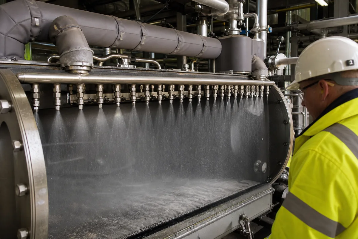
High-pressure nozzle array for melt granulation drums: the steam-jacketed spray header that carries molten sulphur or urea and its row of flat-fan nozzles
Melt granulation drums · steam-jacketed pipe-in-pipe headers, recessed nozzle tubes, 13 to 27 nozzles per header, 50–300 psig melt pressure, separate seed-nozzle feeds
Inside a melt granulation drum, one long header pipe carries the hot melt from the feed end towards the discharge end, and a row of pressure nozzles along it sprays the melt onto the curtains of granules falling from the flights. The header has to keep the melt above its freezing point right up to each orifice while sitting in a stream of cooling air and dust. When buying one, settle three things: how the header and nozzles are heated and shielded, how many nozzles it carries at what spacing, pressure and flow, and whether coating and seed nozzles are fed separately.
Multi-nozzle melt spray headers mounted inside rotary drum granulators for molten sulphur, urea and other melts: the jacketed or insulated header pipe, the nozzle tubes and their mounting, nozzle count, pitch, orientation, pressure and flow per nozzle, inlet screens, and the companion water-spray header where the drum is cooled by water. The drum itself, its flights, deflector pans and curtain-forming internals, its heat balance and the granules it makes are covered on the Rotary granulation drum for urea melt page; slurry distributors and ammonia spargers in NPK drums on the Rotary drum granulator for compound fertilizers page; the spray heads of prill towers on the Prilling tower page. Individual hydraulic and air-atomizing nozzles as catalogue items are covered on the Spray nozzle and Air-atomizing (two-fluid) nozzle pages; other spray-bar arrays have their own pages: felt conditioning showers on paper machines, beverage bottle rinsing nozzles, liquid-nitrogen spray headers in food freezers and hot-water spray zones in pasteurizers.
CNFX editorial research · Sources checked October 13, 2026 · 5 sources
Keeping melt liquid to the orifice: coaxial steam jacket, insulated casing and recessed nozzle tubes
Dow Chemical's patent for a drum-granulator spray header names the failure it set out to stop: nozzle orifices plugging because the melt solidified before it left the nozzle. Earlier headers had nozzles standing out from the pipe; dust landed on those extensions, melted, then froze, and air currents inside the drum cooled the extensions enough to freeze melt inside them. [1]
Dow's answer is two coaxial pipes: melt flows in the inner pipe, and steam or hot oil fills the annular space between it and the outer pipe. Each nozzle assembly is a tube welded through the outer pipe with a smaller tube inside it that is recessed into the outer tube and fed from the melt pipe, so the heating fluid surrounds the nozzle almost to the exit. A curved shoulder on the outer tube lets particles that settle on it melt and drip off instead of falling into the opening. The patent's bisphenol example sprays at 50–200 psig, holds the melt 2–10 °C above its melting point, fits each nozzle with an inlet screen against plugging, and rotates each nozzle slightly off horizontal so the sprays do not overlap. [1]
Enersul's 2021 header for single-pass sulphur granulation keeps the pipe-in-casing idea and insulates the casing: the internal pipe carrying molten sulphur is about 2 in in diameter, on the order of half the diameter of the external casing, ceramic or fibreglass insulation strips are fitted inside the casing, and stainless steel sheet cladding with an opening for each nozzle covers the insulation outside; a hex-head pipe plug secures each nozzle. [2]
Procor Sulphur Services' drum keeps its sulphur header liquid with a surrounding steam jacket and adds a granule deflector shield on top of the header. The patent gives the reason: particles that hit the hot header would melt on it, drip off and resolidify as build-ups on the flights passing beneath. [3]
Ask the header builder whether the nozzles are inside the heated zone up to the orifice or stand proud of it, which heating medium and pressure the jacket is designed for, what shields the top of the header, and how a nozzle is removed and refitted.
02
From 13 nozzles at 2 ft to 27 nozzles at 3 13/16 in: header length, pitch, pressure and flow per nozzle
The published headers differ by an order of magnitude in nozzle spacing, which follows from flow per nozzle. Procor's sulphur drum carries 13 nozzles at 2 ft centres on a header about 24 ft long inside the drum, supplied with liquid sulphur at 40 t/h by a pump at about 300 psig, in an example projected for about 40 t/h of granules. [3] TVA's urea test granulator, 7 ft in diameter and 10 ft long, sprayed urea at 300 °F through 27 hydraulic atomizing nozzles on 3 13/16 in centres at a total of 3,520 lb/h. [5]
Editorial calculation: TVA's 3,520 lb/h over 27 nozzles is about 130 lb/h (about 59 kg/h) per nozzle, and 26 gaps of 3 13/16 in span about 99 in, about 8.3 ft of the 10 ft drum. Procor's 40 t/h of sulphur over 13 nozzles is about 3,080 kg/h per nozzle, near the top of the 500–3,500 kg/h per-nozzle range the patent states. [5][3]
Procor names Spraying Systems flat-fan nozzle types QVV, QU, QLU and TP for the sulphur sprays, at spray angles between about 50 and 110 degrees, aimed roughly horizontally at the falling curtains, and suggests raising the discharge rate along the drum from feed end to discharge end, either by raising nozzle pressure or by fitting larger nozzles towards the discharge end. [3] Enersul shows its coating nozzles set about 5° off horizontal. [2]
Procor also states where the nozzles sit relative to the curtain: 14 to 40 in from the sulphur nozzle to the nearest curtain. [3]
Header and source
Nozzles and spacing
Melt pressure
Flow
Procor sulphur drum
13 at 2 ft centres; header about 24 ft in the drum [3]
1,033–2,065 kPa gauge per nozzle; about 300 psig at the pump in the example [3]
Give the header builder the melt, its melting point and spray temperature, the total melt rate, the drum length and diameter, the number of curtains to be sprayed, the available pump pressure, and whether the rate should rise along the drum.
03
Two internal feed pipes in one casing: coating nozzles and seed-generating nozzles on separate supplies
Enersul's single-pass sulphur header puts two internal pipes inside one external casing. The first feeds the first 25 nozzles from the sulphur inlet, the coating nozzles, which end about two-thirds of the way along the casing; a second internal pipe, not connected to the first, feeds the remaining nozzles, so they can run at a different flow rate and pressure and carry a different nozzle size suited to generating seed. Neither internal pipe has to be coaxial with the casing. [2]
Sandvik's sulphur granulator generates seed outside the drum instead, through 4 to 16 flat-fan nozzles on two seed header conduits spraying into a water tank; one example gives each seed nozzle a 65° flat fan, a 4.4 mm equivalent orifice and 45 psi sulphur pressure, aimed 45° down from horizontal. The supply lines and the drum sulphur header may be steam jacketed, and one pump with a variable-frequency drive supplies both the seed nozzles and the enlargement nozzles inside the drum. [4]
Water headers run beside the melt header in sulphur drums. Procor places a water header on a box beam along the drum with its own deflector shield, a water nozzle for each sulphur nozzle, and spacings of about 10–12 in from the sulphur nozzle to the water spray centreline and about 8–10 in from the water nozzle to the sulphur spray centreline, so that the water spray passes through the sulphur spray without sulphur droplets building up on the water nozzle. Its example uses water nozzles with a 6503 capacity designation giving a flat fan of about 72° at 130 psig. [3] Enersul's water header uses the same internal-pipe-in-casing layout and can likewise be split between two water supplies. [2]
Say whether the header must also make seed, and if so whether the seed nozzles need their own supply, pressure and nozzle size, and whether a water header is to be built alongside.
04
Data for a drum melt spray header
Paste it into your enquiry below or into an email to a maker, then replace every bracket.
Melt: [sulphur, urea or other; melting point; spray temperature; solids or additives]
Rate: [total melt flow; flow per nozzle; rising along the drum or uniform]
Drum: [diameter; length; number of curtains; nozzle-to-curtain distance]
Header: [steam jacket, hot oil or insulated casing; jacket pressure; pipe sizes]
Nozzles: [type; spray angle; count; spacing; orientation; inlet screens]
Feeds: [single supply or separate coating and seed pipes]
Water header: [needed or not; nozzle spacing; pressure]
Access: [nozzle removal method; header withdrawal from the drum]
Explore company information and manufacturing capabilities, then discuss the scope of your project with a relevant supplier.
Share this page
Compiled and source-reviewed by the CNFX editorial team.
Each manufacturer above links to the page on that company's own website where the product is listed, with the date we checked it. How we source and review
· Page last updated 13 October 2026
Buyer questions
Why do melt spray nozzles in a granulation drum plug?
Dow's patent attributes plugging to melt freezing before it leaves the nozzle: dust melts and refreezes on nozzle extensions, and drum air cools nozzles that stand out from the heated header. [1]
How many nozzles does a drum melt header carry?
Published examples range from 13 sulphur nozzles at 2 ft centres in Procor's drum to 27 urea nozzles on 3 13/16 in centres in TVA's 10 ft test drum. [3][5]
What pressure is molten sulphur sprayed at in a granulation drum?
Procor states about 1,033–2,065 kPa gauge at the nozzles for 500–3,500 kg/h each, with about 300 psig at the pump in its example. [3]
Can one header feed both coating and seed nozzles?
Enersul's header carries two separate internal pipes in one casing, so the seed nozzles can run at their own flow, pressure and nozzle size. [2]
Sources and what still needs a direct check
Sources checked 2026-10-13. Five patents from five applicants: Dow Chemical (jacketed header with recessed nozzles), Enersul (insulated casing with two internal pipes), Procor Sulphur Services (sulphur and water headers, nozzle pressure and flow), Sandvik Process Systems (nozzle spacing and seed nozzles) and the Tennessee Valley Authority (urea nozzle count and spacing in a test drum).