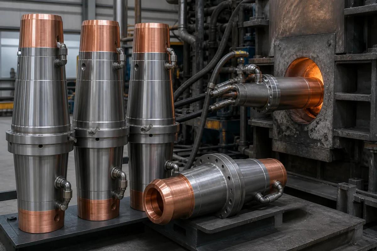
Water-cooled nozzle body for electric arc furnace burners and oxygen injectors: the copper-tipped, water-jacketed body that holds a supersonic nozzle in the furnace wall
Electric arc furnace · the water-cooled metal body that carries an oxygen or burner nozzle through the furnace wall: copper tip, cooling passages, supersonic nozzle bore and the cast block it sits in
An oxygen injector or burner that fires into an electric arc furnace from a fixed position in the wall has its nozzle a short distance from scrap, slag and arc radiation for the whole heat. What keeps it alive is the body around the nozzle: a metal casing, tipped in copper, with water passages that carry the heat away, and a block or panel that holds it at the right angle to the bath. This page covers that water-cooled body, the nozzle bore it carries and the way it is mounted and cooled.
Water-cooled metal bodies of wall-mounted burners, burner-injectors and supersonic oxygen injectors for electric arc furnaces: the copper or copper-tipped casing, its cooling water passages and connections, the supersonic nozzle bore inside it, and the cast panel or block that holds it in the furnace wall. Refractory nozzles that carry molten steel out of ladles and tundishes are covered on the Molten metal flow control nozzle page, stopper-rod valves that dose cast metal on the Stopper-rod pouring valve for foundry pouring furnaces and bottom-pour launders page, and submerged entry nozzles on their own page; movable lances and their manipulators on the Lance manipulator for electric arc furnace oxygen and carbon lances page; cooling skids for steelmaking lances on the Oxygen lance cooling water system page; fuel burners for industrial furnaces on the Industrial burner page; the furnace as a whole on the Electric arc furnace page and refractory burner blocks on the Burner assembly page; blast furnace gas burner nozzles on their own page.
CNFX editorial research · Sources checked October 13, 2026 · 3 sources
The supersonic nozzle inside the body: downward angle, oxygen pressure and why a Laval bore alone can destroy the body
American Combustion's US patent 5,843,368 for electric steelmaking describes a liquid-cooled burner-injector body whose additional oxygen nozzle is a converging-diverging (supersonic) section followed by a stepped flow-enhancing channel. [1]
The patent gives the reason for the stepped channel in terms of the body itself: a conventional Laval nozzle holds a stable stream only in a very narrow band of gas flow, and outside it the jet destabilises and draws slag and molten metal into the discharge nozzle, which the patent says leads to rapid destruction of the burner-injector body and splashing of metal. [1] The stepped zones are claimed to keep the jet stable over a wide flow range covering subsonic and supersonic operation. [1]
Linde describes the result that a fixed wall injector is meant to deliver: its COJET nozzle, mounted in the furnace wall, produces a coherent oxygen jet of 3 to 5 ft at supersonic speed that keeps its original diameter and velocity to the bath, and the same nozzle works as a sidewall burner for scrap melting and as an oxygen source for post-combustion, which Linde says removes the need for lance manipulators. [3] Editorial conversion: 3 to 5 ft is about 0.9 to 1.5 m.
Design value in US 5,843,368
Stated range
Angle of the supersonic section below the body's central axis
Ask the injector supplier for the nozzle throat and exit diameters, the design oxygen flow and pressure band over which the jet is stable, the angle of the bore relative to the body and to the bath, and how the nozzle tip is protected when the jet is turned down to burner or idle flow.
02
Water passages and the wall block: slotted water heads, guide ribs and a helical copper circuit round the injector chamber
Air Liquide's European patent EP 2 495 519 lists what a burner or injector in an EAF has to survive: intense radiant heat, convective heat from hot furnace gases, slagging from splashing slag and blowback of injected oxygen, which is why such units are mounted in panels that shield them, sometimes water-cooled. [2]
In the American Combustion design the cooling water is fed through a water separating head with input slots, which directs water forward along the inner surface to cool the walls of the mixing chamber, the supersonic section and the flow-enhancing sections; guiding ribs on that inner surface spread the water to avoid local overheating. [1] Supply and return run between the outer water-cooled pipe and a partitioning conduit, with a separate inlet and outlet for the cooling water. [1]
Air Liquide's patent puts the burner or injector in a cylindrical chamber through a main body with a flange, which may be any metal suitable for an EAF; the patent names copper or copper alloy. [2] Its cooling circuit runs from an inlet down a leg, through a helical portion wound around the chamber, and back up a return leg to the outlet; the patent says this cools the burner or injector better than conventional serpentine panels because the circuit goes 360° round the chamber instead of one side of it, and that the circuit dimensions are designed for the thermal load expected on the body. [2] One way of making it is to bend a copper or copper-alloy pipe into the coil and legs and cast the body around it. [2]
The same patent mounts the body through a circular opening in a water-cooled furnace panel, with the opening large enough for the angled body to be turned at least 90° without striking the panel, and in the patent's preferred forms 180° or a full 360°, and holds the flange down with studs, retaining clips and fasteners on a plate. [2] The patent's stated aim is that the aim of a sump burner or injector at a target area of the bath, such as a cold spot, can be changed without shutting the furnace down to uninstall, redesign and reinstall the panel apparatus or enlarge its opening. [2]
Specify the cooling water flow and pressure the body needs, the allowable outlet temperature, the alarm on low flow or high return temperature, the copper grade at the hot face, and how the body is fixed and turned in its panel or block.
03
What to send with an enquiry for an EAF injector or burner nozzle body
Paste it into your enquiry below or into an email to a maker, then replace every bracket.
Furnace: [EAF size; wall, balcony or door position; height above bath]
Duty: [oxygen injection; burner; carbon or lime injection through the same body]
Nozzle: [oxygen flow and pressure; supersonic or subsonic; bore angle]
Body: [copper tip or full copper; steel parts; length into the furnace]
Cooling: [water flow; pressure; inlet and maximum outlet temperature; connections]
Mounting: [panel or block opening; flange; rotation needed]
Spares: [replaceable tips; repair of the copper face]
Explore company information and manufacturing capabilities, then discuss the scope of your project with a relevant supplier.
Share this page
Compiled and source-reviewed by the CNFX editorial team.
Each manufacturer above links to the page on that company's own website where the product is listed, with the date we checked it. How we source and review
· Page last updated 13 October 2026
Buyer questions
At what angle is the oxygen nozzle set in an EAF burner-injector body?
American Combustion's patent places the supersonic section 5° to 45° below the body's axis, with 15° to 30° more preferred, so that the oxygen strikes the melt at about 30° to 55°. [1]
Why can a supersonic nozzle damage its own body?
US 5,843,368 says a conventional Laval nozzle is stable only in a narrow flow band; outside it slag and metal are drawn into the discharge nozzle and the body is destroyed rapidly. [1]
How long is the jet from a fixed wall oxygen injector?
Linde describes its COJET wall-mounted nozzle as delivering a 3 to 5 ft coherent supersonic oxygen jet into the bath. [3]
How is the body of a wall burner or injector cooled?
Air Liquide's EP 2 495 519 casts a copper body round a helical cooling circuit that goes 360° around the injector chamber; American Combustion uses a slotted water head and guide ribs along the inner surface. [2][1]
Sources and what still needs a direct check
Sources checked 2026-10-13. Two patents, one from American Combustion and one from Air Liquide, describe their own injector nozzle and cooled-body designs; Linde's page describes its own wall-mounted injector system.