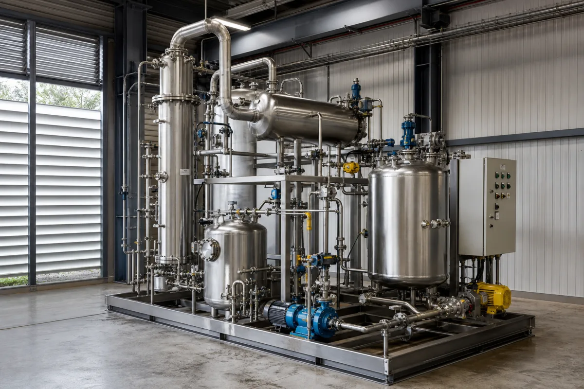
Continuous solvent recovery and purification system (column-based distillation skid)
Continuous column-based solvent recovery skids · Dewatering, solvent evaporation and product rectification, membrane hybrids, heat integration and purity targets
This page covers continuous, column-based systems that take a spent solvent stream, remove water and residue, and rectify the solvent back to a purity the process can reuse, all on an automated skid. Ask three things first: which distillation stages the system uses for your stream, whether an azeotrope or heat-sensitive component calls for a membrane, extraction or pressure-swing step, and what purity and recovery the supplier will state for your feed.
Continuous distillation-column solvent recovery and purification skids for plant process streams, including dewatering, solvent evaporation and product rectification stages and hybrid membrane or extraction steps. Batch solvent recyclers that boil off a charge in a still are covered on the Solvent recovery module page. Activated-carbon vapour recovery, exhaust-air NMP condensation systems and solvent-free parts washers are outside this page.
CNFX editorial research · Sources checked October 12, 2026 · 5 sources
Plan the distillation train: dewatering, solvent evaporation and product rectification
A continuous recovery system splits the job into stages. Sichuan Forever describes its stripping-liquid solvent recovery process in three steps: primary distillation to remove water from the raw material; secondary distillation to evaporate the recoverable solvent completely into vapour and separate the residue; and tertiary distillation, the product distillation, aimed at improving the colour and purity of the product. [1]
Forever lists its automated SRS/PRS waste stripping liquid regeneration system at 600 L/h, with a delivery time of 3–4 months and a supply ability of 20 sets per year, and names LCD panel stripping liquid regeneration, isopropanol aqueous solution distillation and methanol aqueous solution distillation among its process packages. [2] Editorial calculation: 600 L/h over a 24-hour day is 14,400 L of feed per day.
The iScience review by Aboagye and co-authors (2021) states that distillation separates components "at a wide range of flow rates, regardless of the initial concentration, and with high purity", and that fractional distillation is used to separate multiple volatile components where azeotropes are not present. [3]
Give the supplier a full analysis of the spent solvent (components, water, dissolved solids, polymers, photoresist or other residues), the flow in L/h or kg/h, the purity and water limit the recovered solvent must meet, and the utilities available (steam or thermal oil, cooling water, vacuum).
02
Choose the separation route: plain distillation, membranes, extraction or heat integration
Azeotropes and water change the route. A 2023 Ind. Eng. Chem. Res. paper describing a solvent recovery design tool modelled a 1,000 kg/h stream of 51% isopropanol and 49% water with targets of at least 99.5% IPA purity and 99.0% water recovery; the optimized pathway was a pervaporation route (BYP1-BYP2-PVP2-PVP3, where PVP is pervaporation and BYP is bypass), costing $323,000 per year against an estimated $8.1 million per year for incineration. [4]
The same case returned 460.28 kg/h of isopropanol at 99.7% purity and 90.3% recovery, with 488.78 kg/h of water at 91% purity in the disposable stream. [4] Editorial calculation: 460.28 ÷ 510 kg/h of IPA fed = 90.3% recovery, matching the paper; the remaining 49.73 kg/h of IPA leaves with the water.
For energy, the iScience review reports that retrofitting an existing distillation column with a dividing wall can reduce operation and capital cost by up to 20–50%, and that Chaniago et al. (2015), recovering a semiconductor waste solvent mixture containing photoresist, observed about 40% energy savings by thermally coupling the columns in sequence and adding a heat pump. [3]
Sulzer lists pressure swing distillation, membrane separation and extractive or entrainer distillation for azeotropes; vacuum distillation, liquid-liquid extraction and fractional crystallization for heat-sensitive chemicals; heat integration; and skid-mounted units to limit downtime. [5]
03
Three-stage trains, heat-pump coupling, dividing-wall columns and pervaporation hybrids
The configuration follows from the stream; ask the supplier which one it proposes and why.
Configuration
What the source states
When to ask for it
Three-stage distillation train
Dewatering, solvent evaporation with residue separation, product distillation for colour and purity. [1]
Wet streams with dissolved residue, e.g. stripping liquids.
Thermally coupled columns with heat pump
About 40% energy savings in a semiconductor waste-solvent study. [3]
Large continuous flows with high reboiler duty.
Dividing-wall column
Retrofit can cut operation and capital cost by up to 20–50%. [3]
Compare continuous solvent recovery system suppliers
1 company lists this product among what they make. Company figures are quoted from each
company's own website; every card states where the relationship came from.
Sichuan Forever Chemical Engineering Technology Co.,Ltd.
Manufacturing site to be confirmed for the order
Lists a 600 L/h LCD panel solvent recovery and solution regeneration system with primary, secondary and tertiary distillation.
Explore company information and manufacturing capabilities, then discuss the scope of your project with a relevant supplier.
Share this page
Compiled and source-reviewed by the CNFX editorial team.
Each manufacturer above links to the page on that company's own website where the product is listed, with the date we checked it. How we source and review
· Page last updated 13 October 2026
Buyer questions
How pure can recovered isopropanol be?
In a 2023 Ind. Eng. Chem. Res. case study, a 51% IPA–49% water stream was recovered to 99.7% IPA at 90.3% recovery using a pervaporation route. [4]
What stages does a continuous solvent recovery system use?
Forever describes primary distillation to remove water, secondary distillation to evaporate the solvent and separate residue, and tertiary product distillation for colour and purity. [1]
Can heat integration reduce energy use?
The iScience review cites about 40% energy savings from thermally coupled columns with a heat pump, and up to 20–50% lower operation and capital cost from dividing-wall retrofits. [3]
Sources and what still needs a direct check
Sources checked 2026-10-12. Forever and Sulzer describe their own systems; the iScience review and the Ind. Eng. Chem. Res. paper are peer-reviewed studies, and the latter's figures are a modelled case, not a plant guarantee.