Editorial Technical Reference

Angular Adjustment Joint

This page explains how Angular Adjustment Joint is classified within Computer, Electronic and Optical Product Manufacturing. Technical values and manufacturer relationships are research references; confirm the current specification and supplier evidence for each order.

Technical Definition & Core Assembly

A mechanical joint that allows precise angular adjustment of antenna positioning within an internal mounting system.
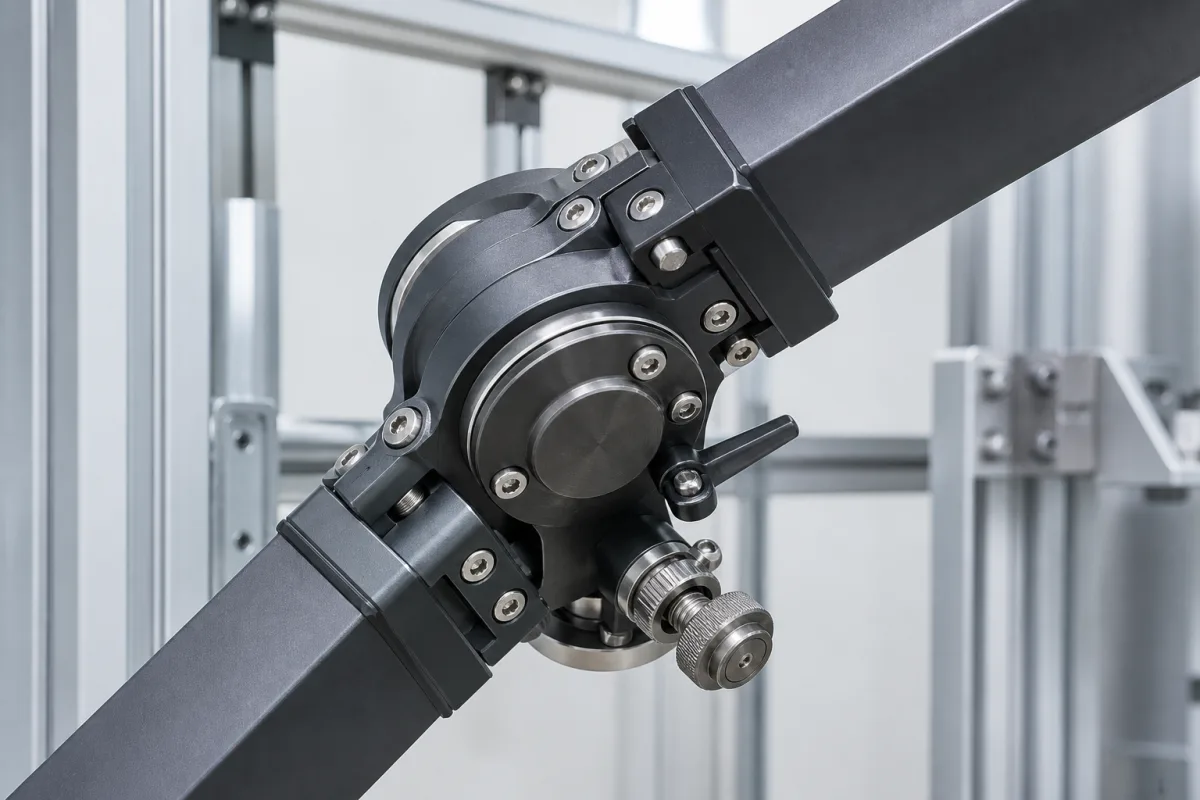
Angular Adjustment Joint in a manufacturing environment
Representative product image. Confirm appearance and specifications with the manufacturer.

Product Specifications

Technical details and manufacturing context for Angular Adjustment Joint

Definition
The Angular Adjustment Joint is a critical component of the Internal Antenna Mounting System that enables fine-tuning of antenna orientation through controlled angular movement. It provides the mechanical interface between fixed mounting structures and adjustable antenna elements, allowing operators to achieve optimal signal reception and transmission angles while maintaining structural integrity within enclosed spaces. The joint is designed for use in computer, electronic, and optical product manufacturing, specifically for antenna systems that require precise alignment. It is available in aluminum alloy (6061-T6) and stainless steel, with surface treatment options including hard anodizing (10–25 μm) per MIL-A-8625. The adjustment range is ±45°, with a repeatability of ±0.1° and backlash of ≤0.2° after locking. The joint can handle axial loads of 500–2000 N and radial loads of 300–1500 N, and operates within a temperature range of -40°C to 85°C. It offers ingress protection rated IP65–IP67 per IEC 60529, making it suitable for outdoor antenna systems. Thread sizes for mounting are M8–M12 per ISO 68-1, and the weight ranges from 0.5 to 2.0 kg depending on size and configuration. The required torque to secure the joint after adjustment is 5–20 N·m. These values are reference ranges and must be verified for the specific model and application. The joint is a component, not a standalone product, and should be integrated into a complete mounting system. For procurement, verify model-specific parameters and compliance with relevant standards with the legal manufacturer or supplier.
Working Principle
The joint operates through a combination of precision-machined mating surfaces and adjustable fastening mechanisms. By loosening locking components, the joint allows rotational movement along one or more axes, then securely locks into position once the desired angle is achieved. This enables precise angular positioning without compromising structural stability. The adjustment is achieved by turning a threaded mechanism or using a tool to loosen and tighten the fasteners, allowing incremental movement. The locking mechanism ensures that the set angle is maintained under load, with minimal backlash. The joint is designed to provide repeatable angular settings, making it suitable for applications where consistent antenna alignment is critical.
Common Materials
Aluminum alloy, Stainless steel
Technical Parameters
ParameterTypical rangeNotes & selection driver
Adjustment Range±45 °Angular travel for antenna alignment
Torque5–20 N·mRequired to secure joint after adjustment
Axial Load Capacity500–2000 NMaximum axial force without deformation
Radial Load Capacity300–1500 NMaximum radial force without deflection
Operating Temperature-40–85 °CSuitable for outdoor antenna systems
Ingress ProtectionIP65–IP67Dust-tight and protected against water jetsIEC 60529
Material6061-T6Aluminum alloy for corrosion resistanceASTM B211
Surface TreatmentAnodized 10–25 μmHard anodizing for wear resistanceMIL-A-8625
Weight0.5–2.0 kgDepends on size and configuration
Thread SizeM8–M12Mounting holes for bracket attachmentISO 68-1
Repeatability±0.1 °Consistency of angular setting
Backlash≤0.2 °Angular play after locking

Ranges are indicative industry figures for RFQ preparation, not a supplier commitment. Confirm every value and standard with the legal manufacturer before ordering.

Components / BOM

Applied To / Applications

This component is essential for the following industrial systems and equipment:

Industrial Ecosystem & Supply Chain Structure

Complementary Systems
Downstream Applications
Specialized Tooling

Application Fit & Sizing Matrix

Operational Limits
pressure: 0 to 2 bar (non-pressurized system)
other spec: Angular range: ±15°, Torque capacity: 50 Nm max, Vibration resistance: 5g RMS
temperature: -40°C to +85°C
Media Compatibility
✓ Antenna mounting structures (aluminum/steel) ✓ RF transmission lines (coaxial cables) ✓ Outdoor enclosure systems (IP65+ rated)
Unsuitable: High-pressure hydraulic systems or corrosive chemical environments
Sizing Data Required
  • Required angular adjustment range (± degrees)
  • Antenna weight and wind load moment (Nm)
  • Mounting interface dimensions and bolt pattern

Reliability & Engineering Risk Analysis

Failure Mode & Root Cause
Bolt fatigue fracture
Cause: Cyclic loading from vibration or misalignment exceeding bolt yield strength, often due to improper torque or inadequate preload
Bearing surface fretting corrosion
Cause: Micro-motion between mating surfaces under load, combined with environmental contaminants, leading to material degradation and loss of angular precision
Maintenance Indicators
  • Audible clicking or popping during rotation under load
  • Visible angular drift or inability to maintain set position during operation
Engineering Tips
  • Implement precision laser alignment during installation and periodic verification to minimize parasitic loads
  • Apply anti-seize compound with corrosion inhibitors to bolt threads and mating surfaces, following manufacturer's torque specifications with calibrated tools

Indicative industry ranges for design and RFQ preparation. Confirm the exact figures and applicable standard with the manufacturer before specifying.

Compliance & Manufacturing Standards

Applicable Standards
ASTM A370 - Standard Test Methods and Definitions for Mechanical Testing of Steel Products CE Marking - Directive 2006/42/EC on machinery safety

Quoted from the published standard.

Manufacturing Precision
  • Angular adjustment range: +/- 0.5 degrees
  • Surface flatness at mounting interface: 0.05 mm
Quality Inspection
  • Dimensional verification using coordinate measuring machine (CMM)
  • Hardness testing per ASTM E18

Manufacturers of Angular Adjustment Joint

Manufacturer profiles associated with Angular Adjustment Joint.

Sourcing Angular Adjustment Joint from China?
Tell us your specification and target quantity — we will match it against manufacturer records and come back with the factories that fit.
Request manufacturers We manufacture this

Manufacturer listings support early research and capability understanding. They are not certification, ranking, or transaction guarantees.

Share this page
Technical documentation
Request current drawings, revision history, and a signed specification sheet.
Manufacturing capability
Verify equipment lists, process limits, capacity, and representative production evidence.
Inspection readiness
Confirm test methods, calibrated equipment, sampling plans, and traceable reports.
Supplier transparency
Check the legal entity, factory address, ownership, certifications, and direct contacts.

CNFX does not score or rank suppliers. Buyers must verify all claims and documents with the legal manufacturer before ordering.

Supply Chain Compatible Machinery & Devices

Industrial IoT Gateway

The Industrial IoT Gateway is a ruggedized edge computing device designed for industrial environments.

Explore Specs →
Modular Industrial Edge Computing Device

This modular industrial edge computing device is a ruggedized system designed for deployment in harsh industrial environments to perform real-time data processing, analytics, and control functions at the network edge.

Explore Specs →
Industrial Smart Camera Module

The Industrial Smart Camera Module is a compact, self-contained vision processing unit designed for integration into industrial machinery and production lines.

Explore Specs →
Surface Mount Resistor

Passive electronic component for current limiting and voltage division in circuits

Explore Specs →

Frequently Asked Questions

What is the adjustment range of the Angular Adjustment Joint?

The adjustment range is ±45° for antenna alignment. This allows for fine-tuning of the antenna orientation within the mounting system. The exact range may vary by model, so verify with the manufacturer.

What materials are available for this joint?

The joint is available in aluminum alloy (6061-T6) and stainless steel. The aluminum version can have hard anodizing (10–25 μm) for wear resistance. Material selection depends on the application requirements.

What is the ingress protection rating?

The joint is rated IP65–IP67 per IEC 60529, meaning it is dust-tight and protected against water jets. This makes it suitable for outdoor antenna systems. Confirm the specific rating for your model.

How is the joint locked after adjustment?

The joint is locked by tightening the fastening mechanism to a specified torque of 5–20 N·m. This secures the joint in position and minimizes backlash (≤0.2°). Always follow the manufacturer's instructions for proper locking.

Data Basis

Editorial classification, named public sources where available, and source-reviewed manufacturer records.

Preliminary Technical Classification
This page supports structured research, RFQ preparation, and supplier evaluation. It does not replace buyer-led supplier qualification, standards review, or technical approval.
Buyer enquiry

Request manufacturing insight for Angular Adjustment Joint

Ask for use case, specification boundaries, supplier type, and RFQ preparation information for this product.

Where it goes
Straight to the CNFX editorial desk, and to the manufacturer if this product is linked to a claimed profile. Nothing is broadcast to a supplier list.
Your details stay here
We do not sell or rent enquiry data, and we do not add you to a mailing list. Used only to answer this request.
No commission, no middleman
CNFX is a directory. We take no cut of any order and never negotiate on a supplier's behalf.
What we don't claim
A listing is not an endorsement. Qualify every supplier and verify every figure yourself before ordering.

Your business information is used only to process this request.

Thank you! Your message has been sent. We'll respond within 1–3 business days.
Sorry, we couldn't send your message. Please try again, or email us at [email protected].

Need to Manufacture Angular Adjustment Joint?

Compare manufacturer profiles with relevant product and process capability.

Previous Product
XY Positioning Stage
Last Product
Get QuotesChat