Editorial Technical Reference

Signal Processing Electronics

This page explains how Signal Processing Electronics is classified within Computer, Electronic and Optical Product Manufacturing. Technical values and manufacturer relationships are research references; confirm the current specification and supplier evidence for each order.

Technical Definition & Core Assembly

Electronic subsystem that processes sensor signals for beam monitoring applications
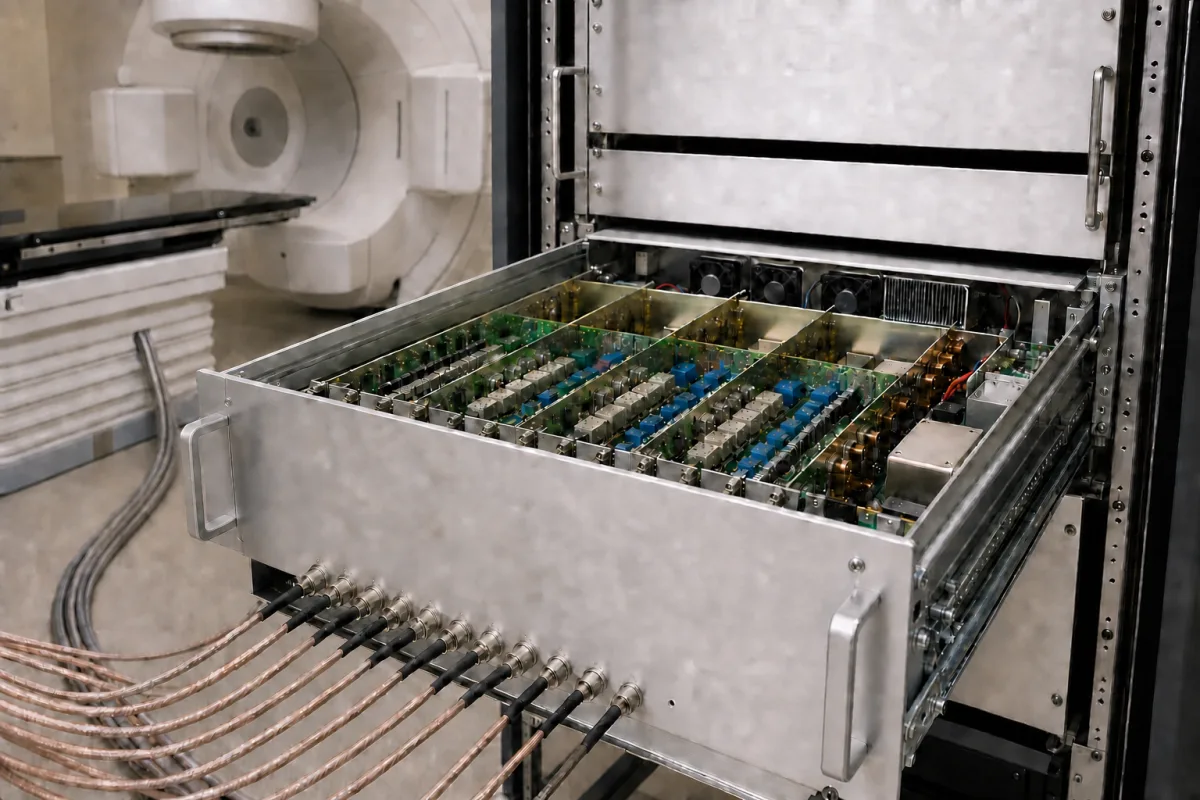
Representative product image. Confirm appearance and specifications with the manufacturer.

Product Specifications

Technical details and manufacturing context for Signal Processing Electronics

Definition
This product is a specialized electronic component within a Beam Monitoring System, designed for particle accelerator or beamline environments. It receives low-level analog signals from beam sensors such as beam position monitors, current transformers, or scintillators. The subsystem performs signal conditioning, including amplification, filtering, and noise reduction, to prepare the signals for accurate digitization. It then converts the conditioned analog signals into digital data using an analog-to-digital converter (ADC) with a resolution of 16 to 24 bits. The digital output is transmitted to the system's control and data acquisition units for real-time monitoring, analysis, and feedback control. The component supports 8 to 32 input channels, with a per-channel sampling rate of 100 to 500 kS/s. It offers a programmable input voltage range of ±10 V and a small-signal bandwidth of 10 to 100 kHz. The signal-to-noise ratio is at least 80 dB at full scale. The operating temperature range is -40 to 85 °C, tested according to IEC 60068-2-1/2. The supply voltage accepts 9 to 36 V DC, and power consumption is typically 15 W or less at full load. The enclosure provides ingress protection rated IP54 to IP65 per IEC 60529, suitable for industrial environments. Dimensions are 200×150×50 mm, and weight is 2.5 kg or less without cables. The materials include a printed circuit board, semiconductor components (ICs, transistors), passive components (resistors, capacitors, inductors), and connectors and wiring. This product is a component intended for integration into a larger system. All listed parameters are reference ranges; verify model-specific values and standards with the legal manufacturer or supplier before procurement.
Working Principle
The subsystem receives low-level analog signals from beam sensors. It applies signal conditioning, including amplification, filtering, and noise reduction, to improve signal quality. The conditioned signals are then converted to digital form using an analog-to-digital converter. The digital output is sent to control and data acquisition units for real-time monitoring and feedback control. The gain is programmable, and the input voltage range is ±10 V. The ADC resolution is 16 to 24 bits, and the sampling rate is 100 to 500 kS/s per channel. The bandwidth is 10 to 100 kHz, and the signal-to-noise ratio is at least 80 dB at full scale. The subsystem operates over a temperature range of -40 to 85 °C and accepts a supply voltage of 9 to 36 V DC. Power consumption is typically 15 W or less at full load.
Common Materials
Printed Circuit Board (PCB), Semiconductor components (ICs, transistors), Passive components (resistors, capacitors, inductors), Connectors and wiring
Technical Parameters
ParameterTypical rangeNotes & selection driver
Input Signal Channels8–32 chNumber of sensor inputs supported
Sampling Rate100–500 kS/sPer channel, simultaneous
ADC Resolution16–24 bitHigher resolution for low-level signals
Input Voltage Range±10 VProgrammable gain
Bandwidth10–100 kHzSmall-signal bandwidth
Signal-to-Noise Ratio≥80 dBAt full scale
Operating Temperature-40–85 °CExtended temperature rangeIEC 60068-2-1/2
Supply Voltage9–36 V DCWide input range
Power Consumption≤15 WTypical at full load
Ingress ProtectionIP54–IP65For industrial environmentsIEC 60529
Dimensions200×150×50 mmEnclosure size
Weight≤2.5 kgWithout cables

Ranges are indicative industry figures for RFQ preparation, not a supplier commitment. Confirm every value and standard with the legal manufacturer before ordering.

Components / BOM
  • Analog Front-End
    Receives and conditions raw analog signals from sensors with amplification and filtering
    Material: PCB with analog ICs and passive components
  • Analog-to-Digital Converter (ADC)
    Converts conditioned analog signals to digital data for processing
    Material: Semiconductor ADC chip with supporting circuitry
  • Digital Signal Processor (DSP)
    Processes digitized signals with algorithms for filtering, analysis, and feature extraction
    Material: DSP chip or FPGA with memory
  • Power Supply Unit
    Provides regulated power to all electronic components
    Material: Power regulation ICs, capacitors, and transformers
  • Communication Interface
    Enables data transmission to control systems via standard protocols (Ethernet, USB, etc.)
    Material: Communication ICs and connectors

Applied To / Applications

This component is essential for the following industrial systems and equipment:

Industrial Ecosystem & Supply Chain Structure

Complementary Systems
Downstream Applications
Specialized Tooling

Application Fit & Sizing Matrix

Operational Limits
pressure: Not applicable (electronic subsystem)
other spec: Input signal range: ±10V, ±20mA; Power supply: 24VDC ±10%; EMI/EMC compliance: IEC 61326-1
temperature: -40°C to +85°C
Media Compatibility
✓ Clean room environments ✓ Laboratory test setups ✓ Industrial control cabinets
Unsuitable: High-vibration, high-shock environments (e.g., heavy machinery mounts)
Sizing Data Required
  • Sensor output signal type and range (e.g., voltage, current, frequency)
  • Required signal processing bandwidth and sampling rate
  • Number of sensor channels to be processed simultaneously

Reliability & Engineering Risk Analysis

Failure Mode & Root Cause
Thermal degradation of components
Cause: Inadequate heat dissipation leading to overheating of semiconductors, capacitors, and integrated circuits, often due to poor ventilation, excessive ambient temperature, or dust accumulation on heat sinks.
Signal integrity degradation
Cause: Electromagnetic interference (EMI) or radio frequency interference (RFI) from nearby equipment, poor grounding, or degraded connectors/cabling causing noise, signal attenuation, or data corruption.
Maintenance Indicators
  • Intermittent or erratic signal output (e.g., flickering displays, unstable readings, or data dropouts)
  • Audible high-frequency whining or buzzing from transformers, capacitors, or power supplies, indicating component stress or impending failure
Engineering Tips
  • Implement regular thermal monitoring using infrared cameras or temperature sensors on critical components, and maintain clean, unobstructed airflow paths with scheduled cleaning of filters and heat sinks.
  • Use shielded cables, proper grounding techniques, and ferrite beads on signal lines to minimize EMI/RFI, and periodically inspect connectors for corrosion or wear, applying contact cleaner as needed.

Indicative industry ranges for design and RFQ preparation. Confirm the exact figures and applicable standard with the manufacturer before specifying.

Compliance & Manufacturing Standards

Applicable Standards
IEC 61000-6-2:2019 (Electromagnetic compatibility - Generic standards - Immunity standard for industrial environments) CE Marking (EU Directive 2014/30/EU for electromagnetic compatibility)

Quoted from the published standard.

Manufacturing Precision
  • Component Placement Accuracy: +/- 0.1mm on PCB
  • Signal Frequency Tolerance: +/- 0.01% for reference oscillators
Quality Inspection
  • Automated Optical Inspection (AOI) for PCB assembly defects
  • Environmental Stress Screening (ESS) including thermal cycling and vibration testing

Manufacturers of Signal Processing Electronics

Manufacturer profiles associated with Signal Processing Electronics.

Sourcing Signal Processing Electronics from China?
Tell us your specification and target quantity — we will match it against manufacturer records and come back with the factories that fit.
Request manufacturers We manufacture this

Manufacturer listings support early research and capability understanding. They are not certification, ranking, or transaction guarantees.

Technical documentation
Request current drawings, revision history, and a signed specification sheet.
Manufacturing capability
Verify equipment lists, process limits, capacity, and representative production evidence.
Inspection readiness
Confirm test methods, calibrated equipment, sampling plans, and traceable reports.
Supplier transparency
Check the legal entity, factory address, ownership, certifications, and direct contacts.

CNFX does not score or rank suppliers. Buyers must verify all claims and documents with the legal manufacturer before ordering.

Supply Chain Compatible Machinery & Devices

Modular Industrial Edge Computing Device

This modular industrial edge computing device is a ruggedized system designed for deployment in harsh industrial environments to perform real-time data processing, analytics, and control functions at the network edge.

Explore Specs →
Industrial Smart Camera Module

The Industrial Smart Camera Module is a compact, self-contained vision processing unit designed for integration into industrial machinery and production lines.

Explore Specs →
Surface Mount Resistor

Passive electronic component for current limiting and voltage division in circuits

Explore Specs →
Surface Mount Capacitor

A surface mount capacitor is a fundamental electronic component used for energy storage, filtering, coupling, and decoupling in electronic circuits.

Explore Specs →

Frequently Asked Questions

What is the typical input voltage range?

The input voltage range is programmable and specified as ±10 V. Verify the exact range for your model with the manufacturer.

How many sensor inputs does it support?

It supports 8 to 32 input channels. The exact number depends on the specific configuration; confirm with the supplier.

What is the operating temperature range?

The operating temperature range is -40 to 85 °C, tested according to IEC 60068-2-1/2. Ensure your environment is within this range.

What is the ingress protection rating?

The enclosure is rated IP54 to IP65 per IEC 60529, suitable for industrial environments. Verify the rating for your specific model.

Data Basis

Editorial classification, named public sources where available, and source-reviewed manufacturer records.

Preliminary Technical Classification
This page supports structured research, RFQ preparation, and supplier evaluation. It does not replace buyer-led supplier qualification, standards review, or technical approval.
Buyer enquiry

Request manufacturing insight for Signal Processing Electronics

Ask for use case, specification boundaries, supplier type, and RFQ preparation information for this product.

Where it goes
Straight to the CNFX editorial desk, and to the manufacturer if this product is linked to a claimed profile. Nothing is broadcast to a supplier list.
Your details stay here
We do not sell or rent enquiry data, and we do not add you to a mailing list. Used only to answer this request.
No commission, no middleman
CNFX is a directory. We take no cut of any order and never negotiate on a supplier's behalf.
What we don't claim
A listing is not an endorsement. Qualify every supplier and verify every figure yourself before ordering.

Your business information is used only to process this request.

Thank you! Your message has been sent. We'll respond within 1–3 business days.
Sorry, we couldn't send your message. Please try again, or email us at contact@cnfx.com.

Need to Manufacture Signal Processing Electronics?

Compare manufacturer profiles with relevant product and process capability.

Previous Product
XY Positioning Stage
Last Product
Get QuotesChat