Reflection and transmission gratings · grating equation and groove density, resolving power from illuminated width, blaze wavelength and Littrow use
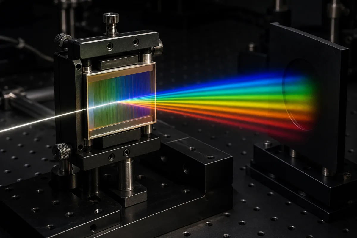
A diffraction grating is an optical surface carrying closely spaced parallel grooves (ruled with a diamond or recorded holographically, with replicas made from the master) that disperses light of different wavelengths into different angles, for spectrometers, monochromators, lasers and wavelength-selective systems. Ask three things first: which groove density and angles your instrument needs for its wavelength range, what resolving power the illuminated width can deliver, and at which wavelength and configuration the grating is blazed for efficiency.
Plane and concave reflection gratings (ruled and holographic, master and replica) and transmission gratings for spectroscopy, lasers and optical instruments. Diffractive beam splitters and other diffractive optical elements, fibre Bragg gratings and decorative grating films are outside this page.
CNFX editorial research · Sources checked October 12, 2026 · 4 sources
Set groove density and angles with the grating equation
The MKS (Newport/Richardson) Diffraction Grating Handbook, 8th edition, gives the grating equation as mλ = d(sin α + sin β), where m is the diffraction order, λ the wavelength, d the groove spacing, α the angle of incidence and β the angle of diffraction. In the Littrow configuration, where the diffracted light returns along the incident direction, it becomes mλ = 2d sin α. [1]
Editorial calculation: a grating with 1,200 grooves per mm has d = 1/1,200 mm ≈ 833.3 nm. Used in first order in Littrow at 500 nm, sin α = 500 / (2 × 833.3) = 0.30, so α ≈ 17.5°. Groove density, order and wavelength are assumed examples; check that every wavelength in your range diffracts to an angle your instrument can collect. [1]
A maker's description of plane ruled gratings explains that a master is ruled by a diamond stylus scribing sawtooth grooves into an aluminium-coated substrate, then replicated by coating the master with a release layer and aluminium and bonding a glass substrate with epoxy resin. [2] Editorial note: ask whether you are buying a master or a replica, ruled or holographic, and for the efficiency curve and stray-light data of the actual part.
Give the supplier the wavelength range, diffraction order, angle of incidence or deviation angle (or Littrow use), required resolution, illuminated width, grating type (plane or concave, ruled or holographic, reflection or transmission), blaze wavelength, coating, size and thickness, polarisation needs and environment.
02
Check resolving power and the blaze wavelength
The handbook gives theoretical resolving power as R = λ/Δλ = mN, where N is the number of grooves illuminated. Rewritten with the grating equation, R depends on the illuminated (ruled) width W and the angles, so the maximum attainable is RMAX = 2W/λ, reached in grazing Littrow use regardless of order or groove count. [1]
For a given blaze angle θB, it defines the blaze wavelength, where efficiency is greatest in Littrow, as λB = (2d/m) sin θB; the first-order Littrow value is λB = 2d sin θB, which is the figure the catalogue example below gives, λB = 2d sin θB, and the blaze wavelength decreases as the off-Littrow angle increases. [1]
Editorial calculation: illuminating 25 mm of a 1,200 g/mm grating covers 30,000 grooves, so first-order R = 30,000, resolving about 600 / 30,000 = 0.02 nm at 600 nm; the maximum for that width at 600 nm is 2 × 25 mm / 600 nm ≈ 83,000. A first-order 500 nm Littrow blaze on 1,200 g/mm needs a blaze angle of about 17.5°. The handbook notes that how much of the theoretical value is attained depends on the grating surface quality, groove spacing uniformity, the system optics and the slit or detector element width; wavefront departures greater than λ/10 cost resolving power. [1]
A catalogue part shows how these quantities are stated. Edmund Optics' 1,200 grooves/mm ruled reflective grating (stock #43-005) lists 25.0 × 25.0 mm (±0.5 mm), 9.50 mm thickness, 90% clear aperture, grooves parallel to the short side and aligned to the edge within ±0.5°, 500 nm blaze wavelength at a 17.45° blaze angle, bare aluminium on float glass, and typical absolute peak efficiency of 85% with a typical average peak efficiency above 74%. [3]
Editorial calculation: with d = 833.3 nm, λB = 2d sin θB gives 2 × 833.3 × sin 17.45° ≈ 500 nm, so the catalogue's blaze angle is the first-order Littrow value, matching the 17.5° worked out above; the 85% figure is a peak at the blaze, so ask for the efficiency curve across your band and polarisation. [3][1]
03
Ask for a measured stray-light value and how it was measured
Shimadzu's LO-RAY-LIGH® plane holographic gratings come with a guaranteed stray-light value, which Shimadzu defines as the ratio of diffracted light intensity to the incident intensity of a 473 nm laser, detected at the mid-point between zero-order and first-order light at a deviation angle 2K of 27°, on its own laser stray-light measuring system. Shimadzu states that these values are less than half those of its conventional gratings. [4]
Shimadzu notes that the blaze wavelength is the design wavelength of maximum efficiency in Littrow mounting and is not guaranteed, and that its relative efficiency curves are representative data, not guaranteed values. [4]
Editorial calculation: on a 60 × 60 mm part, removing a 2 mm strip on each side leaves a 56 × 56 mm effective area, about 3,136 mm² or 87% of the 3,600 mm² face; on a 30 × 30 mm part it leaves 26 × 26 mm, about 75%. A 2λ wavefront at 632.8 nm is about 1.27 µm, twenty times the λ/10 level that the MKS handbook links to loss of resolving power, so ask whether a wavefront specification suits your resolution target. [4][1]
When comparing offers, ask each supplier for stray light as a number with its laser wavelength, detection position and deviation angle, since a figure without these conditions cannot be compared with Shimadzu's 2 × 10⁻⁶. [4]
Suppliers linked to this page list diffraction gratings; each card links to the page reviewed.
Listings include plane ruled, planar holographic, transmission and concave holographic gratings from an optics maker, and diffraction gratings within ranges of diffractive optical elements and filters. Ask each for groove density, blaze, efficiency curves and whether parts are masters or replicas.
05
Trace the grating construction
This is a functional reference built from the sources cited; it is not one maker's specification.
Fill the specification fields with values for your instrument
A diffraction grating quotation needs values for your instrument. The table explains each field, gives published values where a reviewed source states them, and says what to obtain from the supplier.
Explore company information and manufacturing capabilities, then discuss the scope of your project with a relevant supplier.
Share this page
Compiled and source-reviewed by the CNFX editorial team.
Published product pages show what a company offers, not tested performance. Confirm the legal seller, factory and scope for your order. How we source and review
· Page last updated 13 October 2026
Buyer questions
What is the grating equation?
mλ = d(sin α + sin β); in Littrow it becomes mλ = 2d sin α (MKS Diffraction Grating Handbook). [1]
Does more grooves per mm mean higher resolving power?
Not by itself: R = mN, but the maximum is 2W/λ, set by illuminated width and angles, regardless of groove density. [1]
What does blaze wavelength mean?
The wavelength of peak efficiency in Littrow, λB = (2d/m) sin θB; the catalogue example quotes first order. [1]
What blaze angle gives a 500 nm blaze at 1,200 grooves/mm?
About 17.45° in first-order Littrow, as one catalogue grating lists; λB = 2d sin θB with d = 833.3 nm. [3][1]
Sources and what still needs a direct check
Sources checked 2026-10-12. The MKS Diffraction Grating Handbook is a grating maker's technical reference (hosted by a distributor); Fushi's page describes its own manufacturing. Formulas are standard optics; example values are editorial. Shimadzu's LO-RAY-LIGH® specification page adds a guaranteed stray-light value with its measurement conditions.