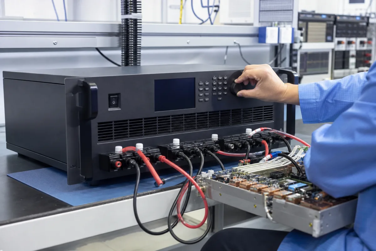
Test power · CV and CC modes, remote sensing, setting and readback accuracy, noise, series and parallel outputs
Set the output voltage and current limit for the device under test, then decide where the supply must regulate and how the test system will program and read it. Include lead resistance, load transients, remote-sense limits and the accuracy terms at the actual operating levels in the purchase specification.
Programmable (remotely controlled) DC power supplies for test and production, single or multi-channel, linear or switching. Fixed-output AC-DC power modules, DIN-rail industrial supplies, AC sources, electronic loads and high-voltage generators are outside this page.
CNFX editorial research · Sources checked October 16, 2026 · 4 sources
Set the supply to work in constant voltage or constant current
Keysight's application note explains that the output runs in constant voltage (CV) mode as long as the load does not draw more current than the current limit; if the load resistance falls below the ratio of the voltage setting to the current limit, the supply regulates current instead (CC mode). An output can become unregulated (UNR) if, among other causes, the AC line is below its range, another source is connected across it, or it is crossing between CV and CC. [1]
Keithley describes CV as regulating the voltage and CC as regulating the current. The operating mode depends on the settings and load resistance; CC can be used as an operating mode as well as a current-limiting response. Maximum voltage, current and power must all support the intended operating point. [2]
Editorial calculation: assuming a steady ideal resistive load, sufficient power capability and negligible lead/internal losses, a supply set to 12 V with a 2 A limit crosses over at Rc = 12/2 = 6 Ω. An assumed 10 Ω load draws 1.2 A in CV; an assumed 4 Ω load gives 2 A and 8 V in CC. This illustrates the ideal CV/CC rule, not manufacturer-published or measured operating data for an instrument. [1]
Keysight also describes over-voltage and over-current protection that turns the output off when the device under test trips it, and list mode that steps voltage or current through programmed values and dwell times on the supply itself without tying up the computer. [1]
Give the supplier the maximum voltage, current and power per channel, number of channels and isolation between them, required setting and readback accuracy, noise limits, load type and transients, lead length and remote sense needs, protection functions, list or sequence mode, interface (LAN, USB, RS-485, GPIB), rack mounting, and AC input.
02
Regulate at the load with remote sensing
Keithley explains that a two-terminal supply regulates at its own output terminals, giving Vload = Vprogrammed − 2 × Iload × Rlead for equal lead resistances. It illustrates a drop of 80–160 mV with 2–4 A through 16-gauge wire, but does not state the lead length in that example. Remote sense extends the feedback loop to the load using high-impedance sense lines; size and assess the actual leads for the installation. [2]
Keysight's example shows 14 AWG leads of 6 ft each at 10 A dropping 0.15 V per lead, 0.3 V in total, so a supply set to 5 V delivers 4.7 V at the load; its wire table gives 2.53 mΩ/ft for 14 AWG and 4.02 mΩ/ft for 16 AWG. It advises twisted shielded sense leads with the shield grounded at one end only, not bundling sense leads with load leads, and avoiding open sense terminals; obtain the selected output’s maximum lead-drop compensation and open-sense behaviour. [1]
Editorial calculation: assuming each lead is 6 ft of the stated 14 AWG wire at 2.53 mΩ/ft, carries a steady 10 A and has no additional connector resistance, 6 × 2.53 ≈ 15.2 mΩ per lead and 10 × 15.2 mΩ ≈ 0.15 V per lead. Both leads together give approximately 0.3 V, reproducing Keysight’s illustration. This is arithmetic from the cited wire table, not a new manufacturer test result or measured operating data. [1]
03
Read setting, readback and noise specifications
Keithley defines setting accuracy as ±(% of setting + offset). Its example specifies ±(0.03% + 3 mV) at 5 V and states a 4.5 mV result, but prints the expression “(5V)(0.0003 + 3mV)”, whose parentheses mix a dimensionless term with millivolts. Confirm that typesetting with the publisher. Editorial calculation: assuming the separately stated accuracy definition is intended, 5 V × 0.0003 + 3 mV = 4.5 mV; this expansion is illustrative, not a measured instrument result. Readback accuracy is a separate ±(% of measured value + offset) specification. Keithley expresses load and line regulation as ±(% of setting + offset) and calls for bandwidth with ripple/noise specifications. [2]
Keysight’s current-readback table gives 0.1–0.5% at 100% of rated current, 0.5–1% at 10% and near 10% at 1%, with the accuracy column identified as typ. Its noise comparison gives approximately 500 µV rms and 4 mV peak-to-peak for a linear supply versus 750 µV rms and 5 mV peak-to-peak for a performance switching supply. That comparison table does not identify a specific model or measurement bandwidth; obtain the selected instrument’s own noise specification and test conditions. [1]
Rohde & Schwarz lists the NGE102B with 2 channels and 66 W total maximum, and the NGE103B with 3 channels and 100 W total maximum. Its channel limits are 0–32 V, up to 3 A and 33.6 W maximum per channel; the voltage, current and power limits must be observed together. The page gives voltage ripple/noise of < 1.5 mV RMS (typ.) and < 20 mV peak-to-peak (meas.), current ripple/noise < 2 mA RMS (meas.), all over 20 Hz–20 MHz. Load recovery is < 200 µs (meas.) for a 10%–90% load change within ±20 mV of the set voltage. Programming/readback resolution is 10 mV / 1 mA; readback accuracy is stated as ±(% of output + offset), with < 0.1% + 20 mV for voltage and < 0.1% + 5 mA for current. Its feature table marks the sense function with “–”; do not assume remote sensing on this range. [4]
Editorial calculation: assuming the cited voltage-readback formula applies at the selected specification conditions, its bound magnitude at 5 V is below 5 V × 0.001 + 20 mV = 25 mV; at 32 V it is below 32 mV + 20 mV = 52 mV. Using the 25 mV boundary value for illustration, the 20 mV offset contributes 80% of that allowance. These are formula evaluations, not manufacturer-published or measured readback errors. [4]
For the selected instrument, request setting accuracy and readback accuracy separately at the intended voltage/current levels, with calibration, temperature and other applicable conditions.
04
Series/parallel output rules and the 9130C channel arrangement
Keysight’s series-connection guidance requires identical output voltage/current ratings, observance of every output’s floating-voltage rating and prevention of reverse voltage. For parallel connection it describes one output in CV and the others in CC, with identical output voltage/current ratings. Obtain the instrument-specific permitted wiring and control arrangement. [1]
B&K Precision’s 9130C series has three independent isolated outputs with series, parallel and tracking functions. Its comparison table lists model maxima of 30 V / 3 A / 195 W for 9130C, 30 V / 6 A / 375 W for 9131C, and 60 V / 3 A / 375 W for 9132C; these are model-level maxima and total power, not identical ratings for every channel. The 9130C description specifies two 0–30 V / 0–3 A outputs and one 0–5 V / 0–3 A output. The series lists 1 mV / 1 mA programming/readback resolution, remote sense, up to 36 stored settings, a timer of 0.1–99999.9 s, USB/RS232 with SCPI, OVP/OTP and a 19-inch half-rack format for two units side by side. [3]
Specify the required voltage and current on each channel at the same operating point, together with per-channel and total power limits. The matching total-power figures of 9131C and 9132C do not make their voltage/current ranges interchangeable. [3]
05
Regulator, converters and the sense-feedback path
Keithley’s programmable linear-supply diagram separates the regulator, DAC setting path, ADC readback path and sense-feedback loop. [2]
Channel ratings, error terms and noise-test bandwidth
State voltage, current and power together for each channel. Keep setting and readback error terms separate, and give the bandwidth for the noise limit.
Request bandwidth and method; Keysight’s comparison gives approximately 500 µV RMS for a linear example. R&S NGE100B gives < 1.5 mV RMS (typ.) / < 20 mV p-p (meas.) over 20 Hz–20 MHz. [1][2][4]
Rms and p-p with bandwidth.
Load regulation (stated basis + offset)
Keithley expresses the change with load as ±(% of setting + offset). [2]
Value.
Line regulation (stated basis + offset)
Keithley expresses the change with AC input as ±(% of setting + offset). [2]
Value.
Programming Resolution
Smallest setting step; e.g. 1 mV / 1 mA on the B&K 9130C series. [2][3]
Voltage and current.
Readback Resolution
Smallest measured change; e.g. 1 mV / 1 mA on the B&K 9130C series. [2][3]
Voltage and current.
Operating Temperature (°C)
Ambient for specified accuracy.
Range.
Storage Temperature (°C)
Non-operating.
Range.
Humidity Range (% RH)
Non-condensing.
Range.
Protection Rating
Enclosure.
IP or rack rating.
Weight (kg)
Rack and bench units.
Weight.
07
Send the load, accuracy and interface data together
Paste it into your enquiry below or into an email to a maker, then replace every bracket.
Outputs: [channels; V; A; W each]
Load: [type; transients; lead length]
Accuracy: [setting; readback at your levels]
Noise: [rms and p-p with bandwidth]
Functions: [remote sense; OVP/OCP; list mode]
Interface: [LAN; USB; RS-485; GPIB]
Mechanics: [bench or rack; AC input]
3 companies list this product among what they make. Company figures are quoted from each
company's own website; every card states where the relationship came from.
Yangzhou Kaihong Power Technology Co., Ltd.
TBC
Lists programmable switching power supplies with DC, AC and high-voltage supplies.
Explore company information and manufacturing capabilities, then discuss the scope of your project with a relevant supplier.
Share this page
Compiled and source-reviewed by the CNFX editorial team.
Each manufacturer above links to the page on that company's own website where the product is listed, with the date we checked it. How we source and review
· Page last updated 13 October 2026
Buyer questions
When does a programmable power supply switch to constant current?
When the load draws more than the current limit, i.e. its resistance is below the voltage setting divided by the current limit. [1]
Why use remote sense?
Keysight’s example uses 6 ft of 14 AWG wire in each output lead at 10 A and shows about 0.3 V total drop. Remote sense regulates at the load within the selected supply’s compensation limits. [1]
How is setting accuracy calculated?
Keithley defines ±(% of setting + offset) and gives a ±4.5 mV result for its ±(0.03% + 3 mV), 5 V example. The worked expression has inconsistent parentheses; the definition gives 5 V × 0.0003 + 3 mV. Confirm the printed expression with the publisher. [2]
What does a multi-channel programmable supply offer in practice?
The 9130C has two 0–30 V / 0–3 A channels and one 0–5 V / 0–3 A channel. The series offers isolated outputs, 1 mV / 1 mA resolution, series/parallel/tracking functions and USB/RS232 with SCPI. Check each channel’s limits for the selected model. [3]
Sources and what still needs a direct check
Sources checked 2026-10-16. Keysight and Keithley are test-instrument makers explaining how their supplies are specified; the Keithley note is an archived copy. B&K Precision's 9130C series page is a manufacturer's published specification for one product range, and the Rohde & Schwarz NGE100B page gives a second maker's ripple, recovery and readback figures. Values for another supply must come from its own data sheet.