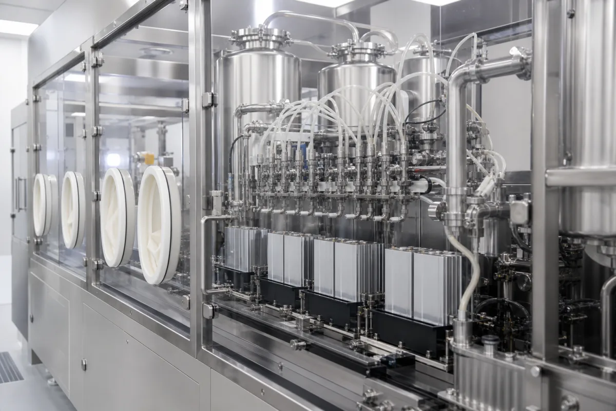
Electrolyte filling machines for lithium-ion cells — cylindrical, prismatic hard-case and pouch · vacuum filling, dosing accuracy and speed, wetting time, electrolyte properties and material compatibility, dry-room dew point, hydrofluoric-acid safety, glove-box enclosure
An electrolyte filling system injects a precise dose of liquid electrolyte into lithium-ion battery cells during assembly, then lets it soak into the electrodes and separator before the cells are sealed and formed. Ask three things first: the cell format and dose per cell, which set the dosing method and speed; the line rate and wetting time, which size the machine and any buffer; and the dry-room conditions and materials needed to handle a moisture-sensitive, hazardous electrolyte.
Electrolyte filling machines and dosing systems for lithium-ion cells — vacuum filling stations for cylindrical, prismatic and pouch cells, dosing pumps, weighing and enclosures — and associated wetting or soaking stations. Electrolyte production plants, formation and ageing equipment, dry-room air systems and complete cell assembly lines are outside this page except where compared.
CNFX editorial research · Sources checked October 12, 2026 · 5 sources
ViscoTec, a dosing-equipment maker, describes filling as the process in which electrolyte is filled into battery cells under vacuum, and wetting as the electrolyte penetrating the porous electrodes and separator so ions can migrate; ViscoTec ranks both among the critical steps for time and quality in cell assembly, and writes that in gigafactories "40 cells per minute is now not uncommon". The electrolyte — a solvent such as ethylene, propylene or dimethyl carbonate with a lithium salt, for which ViscoTec names lithium hexafluorophosphate (LiPF₆) as "the most commonly used lithium salt" — has a density of about 1.1–1.3 g/cm³. [1] For viscosity, a 2026 study from Friedrich Schiller University Jena and Helmholtz Institute Ulm measured 7.00–11.71 mPa·s at 20 °C for four 1 M LiFSI ether–lactone formulations, and cites the benchmark LP30 (1 M LiPF₆ in EC:DMC) at a density of 1.29 g/mL and a flash point of 31 °C. [5] In hard-case cells dosing speed is limited because excessive dosing pressure can destroy the wound cell structure, whereas a pouch can expand briefly at higher speed. Wetting takes between 10 and 45 minutes or more depending on cell size, and unwetted areas leave inactive regions and uneven currents that can cause dendrite growth and short circuits. [1]
Editorial calculation: at 40 cells per minute, each cell has 1.5 seconds of line time, and a 10–45 minute wetting period means about 400–1,800 cells must be held in wetting at once — so the filling station and the wetting buffer must be sized together. [1]
US patent 8,047,241 (Hibar Systems, priority 2008; now assigned to Tesla) shows a vacuum–pressure fill sequence for a battery cell filled through a fill port: the cell and fill head are evacuated to about 5.3 kPa, a pre-metered dose is placed in the chamber above a shut-off plunger, the plunger opens so the vacuum draws electrolyte in, and about 800 kPa is applied above the electrolyte to push the rest in, with the pressure–atmosphere–low-vacuum loop repeated until the full dose has entered. Its example timing is 5 s load, 24 s high vacuum, 1 s vent, 3 s dispense, 1 s vent, 30 s at high pressure, 1 s vent, then 45 s high pressure, 1 s atmosphere and 1 s low vacuum. The patent contrasts this with an older method that injects at up to 196 kPa and fills in 60 s but cannot reach maximum fill levels. [3]
Editorial calculation: the patent's example steps add up to about 112 s per cell at one fill head, so a line running 40 cells per minute (1.5 s per cell) would need roughly 112 ÷ 1.5 ≈ 75 such heads working in parallel; ask suppliers for heads per machine and cycle time on your cell. [3][1]
Vacuum during filling shortens the wetting buffer. The Technical University of Munich's research neutron source FRM II reports a study by Bosch, TUM and the University of Erlangen-Nuremberg (Weydanz et al., Journal of Power Sources 380, 2018) that used neutron imaging, which passes through the metal housing, to watch electrolyte filling of hard-case prismatic cells for hybrid cars. In a vacuum the electrodes were wetted completely in just over 50 minutes against around 100 minutes under normal pressure, with the liquid spreading evenly from all four sides inward, and under normal pressure the electrodes absorbed ten percent less electrolyte; the authors attribute the difference to gas that hinders wetting. The report notes that the filling itself takes only a few seconds, that the process is monitored indirectly by resistance measurement, and quotes Bosch's Wolfgang Weydanz: manufacturers "build in large safety margins" to make sure every pore is filled. [4] Editorial calculation: halving wetting time from about 100 to about 50 minutes halves the number of cells that must sit in the wetting buffer at a given line rate — at 40 cells per minute, about 2,000 instead of 4,000 cells for these prismatic cells. [4][1]
Give the supplier the cell format and dimensions, electrolyte type, viscosity and density, dose per cell and tolerance, required throughput, vacuum and pressure cycle, number of filling heads, weighing before and after filling, wetting or soaking time and method, enclosure (dry room, glove box, inert gas), wetted-part and seal materials, cleaning and electrolyte recovery, safety systems for hydrofluoric acid, integration with upstream and downstream stations, and quantity.
02
Control moisture, materials and hydrofluoric-acid risk
ViscoTec warns that the electrolyte reacts even at low humidity to form hydrofluoric acid, which is acutely dangerous on contact with skin or mucous membranes, so filling is carried out in dry rooms that are complex and expensive to build; dosing equipment must use process-compatible materials and offer long service life under these conditions. [1] Vaisala, a measurement-instrument maker, states that electrode metals, electrolyte and manufacturing chemicals react to moisture, requiring stable low or ultra-low dew-point conditions in dry rooms, dry booths, glove boxes and inert atmospheres, and that maintaining them is essential for safety, yield and efficiency; its dew-point probes for these areas cover −80 °C to +20 °C. [2]
Editorial note: agree the dew point the filling area must hold, how the machine maintains it inside its enclosure, and how leaks and spills of electrolyte are detected and contained — and ask the supplier for its material compatibility list for every wetted part and seal.
03
One maker of prismatic and blade-cell filling machines
Greensun is the company shown below; its listing covers first and second filling stations for prismatic aluminium-case and blade cells.
When requesting quotations, ask each supplier for dose accuracy and repeatability data, cycle time per cell format, vacuum and wetting concepts, enclosure dew point, materials list and reference lines.
Indirect resistance monitoring in production; neutron imaging in research. [4]
Wetting check method and margin.
05
Dose, accuracy, speed, vacuum, dew point and materials for the quotation
Dose, tolerance and seal material have no published value in these sources and must come from the supplier; speed, vacuum, dew point and electrolyte data are shown with their sources.
Field
What it means and published values
Ask the supplier for
Filling volume per cell
Not stated in reviewed sources.
Dose range.
Filling accuracy
Not stated in reviewed sources.
Tolerance, weighing.
Filling speed
ViscoTec: "40 cells per minute is now not uncommon"; ~112 s per cell at one head in one patented sequence. [1][3]
Cells per minute.
Operating pressure / vacuum
Filling under vacuum; e.g. ~5.3 kPa vacuum then ~800 kPa push in one patented method; vacuum cut wetting time to just over 50 min against around 100 min in one prismatic-cell study. [1][3][4]
1 company lists this product among what they make. Company figures are quoted from each
company's own website; every card states where the relationship came from.
Greensun Inc.
Manufacturing site to be confirmed for the order
Lists electrolyte filling machines for prismatic aluminium-case and blade cells, including first and second filling stations.
Explore company information and manufacturing capabilities, then discuss the scope of your project with a relevant supplier.
Share this page
Compiled and source-reviewed by the CNFX editorial team.
Each manufacturer above links to the page on that company's own website where the product is listed, with the date we checked it. How we source and review
· Page last updated 13 October 2026
Buyer questions
How long does electrolyte wetting take?
ViscoTec says 10 to 45 minutes or more depending on cell size. [1]
Why is electrolyte filled in dry rooms?
The electrolyte reacts with even low humidity to form hydrofluoric acid; moisture also harms electrode materials. [1][2]
Why is dosing slower for hard-case cells?
Excessive dosing pressure can destroy the wound cell structure inside a metal casing. [1]
Why do electrolyte fillers alternate vacuum and pressure?
In one patented method the cell is evacuated to about 5.3 kPa so the dose is drawn in, then about 800 kPa pushes the remainder in, repeated until the full dose has entered. [3]
Does filling under vacuum speed up electrolyte wetting?
In a Bosch–TUM neutron imaging study of prismatic cells, electrodes were fully wetted in just over 50 minutes under vacuum against around 100 minutes at normal pressure, and absorbed ten percent less electrolyte at normal pressure. [4]
Sources and what still needs a direct check
Sources checked 2026-10-12. ViscoTec makes dosing equipment and Vaisala makes measurement instruments, both describing the process from their own product perspective; Hibar Systems' patent describes one filling method; TUM's FRM II reports a Bosch–university neutron imaging study of filling and wetting.