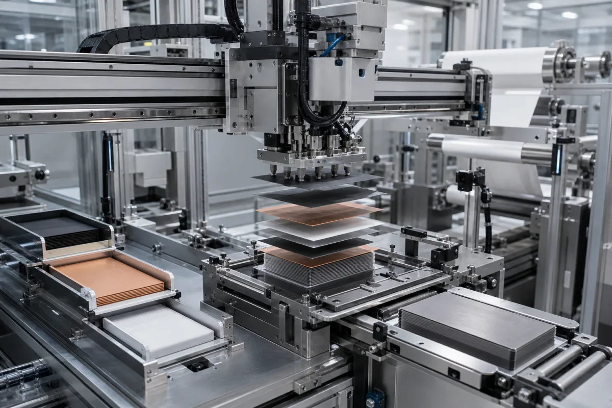
Lithium-ion cell electrode stacking machines · Z-fold and single-sheet stacking, seconds per sheet and stations, tab and separator alignment, separator tension, cell size ranges, integrated notching and stacking, laboratory versus gigafactory machines
An electrode stacking machine builds the core of a stacked lithium-ion cell by placing cut cathode and anode sheets alternately with separator — in Z-fold machines the separator runs as a continuous web folded back and forth between sheets — and aligning every layer before the stack is taped and passed to tab welding and packaging. Ask three things first: what cell format and electrode size the machine must handle, what rate in seconds per sheet the line needs, and what alignment between tabs, electrodes and separator edges the cell design tolerates.
Machines and modules that stack electrode sheets and separator into lithium-ion cell stacks: laboratory and pilot stackers, Z-fold stacking stations and integrated notching (cutting) and stacking machines for pouch, prismatic and blade cells. Winding machines for cylindrical cells, electrode coating, calendering and slitting machines (see battery electrode slitting machine), tab welding, and battery module or pack assembly are outside this page except where compared.
CNFX editorial research · Sources checked October 11, 2026 · 4 sources
A 2025 iScience review of lithium-ion manufacturing equipment describes stacking as layering anode, separator and cathode sheets into a compressed sandwich and names pouch cells and also prismatic cells as stacked formats, while cylindrical cells are wound. It notes that flexible electrodes make pouch stacking prone to wrinkling, misalignment and uneven pressure in bigger stacks, that Z-folding folds the separator in a zigzag to improve alignment and speed, that some machines combine unwinding, punching, marking, lamination, stacking, taping and unloading with web tension control and CCD defect inspection, and that SK Innovation's Gen 3 Z-folding equipment ran 2.3 times faster than its 2010 Gen 1 machines. [1]
Rates are quoted in seconds per sheet (piece). Gweike's dual-station Z-stacking machine for square lithium-ion cells lists 0.6 s per sheet at a single station, 0.3 s per sheet for the whole machine and 6 s or less of auxiliary time per cell. Yinghe's 590-series notching and stacking machine unwinds one cathode and one anode, notches tabs, inspects by CCD, rejects bad electrodes and stacks on three Z-type stations at 0.2 s per sheet (linear layout) or four at 0.15 s per sheet (L-type layout). [2][3]
At laboratory scale, MTI's MSK-111A-EL stacks Z-fashion at up to 5 layers per minute, with electrodes loaded by hand and the stacked cell taped by hand. [4]
Editorial calculation: assuming a cell of 100 electrode sheets, 0.15 s per sheet is 3,600 / 0.15 = 24,000 sheets or about 240 cells per hour, 0.3 s per sheet about 120 cells per hour, and 5 layers per minute (300 per hour) about 3 cells per hour. Divide the line's cell output by these rates to estimate the machines needed. [3][2][4]
Give the supplier the cell format and chemistry, electrode and separator dimensions and thickness, sheets per cell, target cells per hour and yield, whether notching is integrated or sheets arrive pre-cut, stacking method (Z-fold or single sheet, with or without lamination), and downstream taping and handling.
02
Set alignment, separator tension and cell size
Gweike lists alignment accuracy of ±0.2 mm for the separator end face and for adjacent tabs, ±0.3 mm for overall tab alignment, a tab-to-separator centre deviation under 0.3 mm, correction positioning accuracy of 0.1 mm or better and a gripper robot positioning accuracy of ±0.01 mm, with an adjustable number of layers. [2]
Yinghe's 590-series lines handle cells 300–600 mm high, 80–200 or 80–230 mm wide and 5–35 or 5–25 mm thick, in machines of 15,700 × 6,400 × 3,000 mm and 17,300 × 6,800 × 3,000 mm. MTI's laboratory stacker takes pouch cells 200–380 mm long, 100–200 mm wide and up to 15 mm thick, controls separator tension at 5 N or more on separator up to 250 mm wide, aligns stacked electrodes to ±0.5 mm, uses vacuum suction pick-up with a built-in pump to −90 kPa, runs on 208–240 V AC single phase at 1 kW with 0.5–0.8 MPa compressed air, and weighs about 400 kg in a 1,420 × 1,200 × 1,800 mm frame with built-in ESD and dust removal. [3][4]
The review adds that machine vision, tension control and inspection are used to hold alignment and detect defects, and that inadequate or excessive compression during stacking can damage electrode materials. [1]
Ask which feature each alignment figure refers to (separator edge, adjacent tabs, overall stack), how it is measured and on how many cells, the separator tension range and control method, electrode handling (vacuum, gripper), defect inspection and rejection, dry-room or humidity requirements, utilities and footprint.
03
Choose the machine class
The four classes run from a hand-loaded laboratory unit to integrated notching-and-stacking lines; the lamination class comes from the review rather than from a maker's page.
Cutting-and-stacking machines listed by Bozhon and Lead
Bozhon's site lists a three-station cutting and stacking machine, and Lead Intelligent's lists high-speed cutting and stacking machines for EV and energy-storage cells.
05
Gripper, vision, separator tension and notching in a stacker
The notching and inspection row applies to integrated lines such as Yinghe's 590 series, which notch tabs and reject bad electrodes before stacking.
Rate, alignment and size limits to agree for your cell format
A positioning-accuracy figure means little until the supplier says which feature it refers to; Gweike quotes ±0.2 mm for separator end face and adjacent tabs but ±0.3 mm for overall tab alignment.
Field
What it means and published values
Ask the supplier for
Stacking speed
0.6 s/sheet per station; 0.15–0.3 s overall; 5 layers/min lab. [2][3][4]
Rate for your cell and sheets.
Positioning accuracy
±0.2–0.3 mm tabs and separator; ±0.5 mm lab unit. [2][4]
2 companies list this product among what they make. Company figures are quoted from each
company's own website; every card states where the relationship came from.
Bozhon Precision Industry Technology Co., Ltd.
Manufacturing site to be confirmed for the order
Its website lists a three-station cutting and stacking machine.
Explore company information and manufacturing capabilities, then discuss the scope of your project with a relevant supplier.
Share this page
Compiled and source-reviewed by the CNFX editorial team.
Each manufacturer above links to the page on that company's own website where the product is listed, with the date we checked it. How we source and review
· Page last updated 13 October 2026
Buyer questions
How fast do electrode stacking machines run?
Published figures range from 0.6 s per sheet per station to 0.15 s per sheet on four-station lines; a laboratory unit stacks 5 layers per minute. [2][3][4]
Which cells are stacked rather than wound?
The 2025 iScience review describes stacking for pouch cells and also for prismatic cells, while cylindrical cells are wound. [1]
What alignment can a stacking machine hold?
One maker lists ±0.2 mm for separator edges and adjacent tabs and ±0.3 mm overall; ask which feature a figure refers to. [2]
Sources and what still needs a direct check
Sources checked 2026-10-11. The iScience review surveys equipment across makers; the Gweike, Yinghe and MTI pages describe their own machines. Rates and accuracy for your cell must come from the supplier offered and an acceptance test.