Editorial Technical Reference

Vacuum Degassing Chamber

This page explains how Vacuum Degassing Chamber is classified within Electrical Equipment Manufacturing. Technical values and manufacturer relationships are research references; confirm the current specification and supplier evidence for each order.

Technical Definition & Core Assembly

A sealed chamber that removes dissolved gases from electrolyte solutions using vacuum pressure.
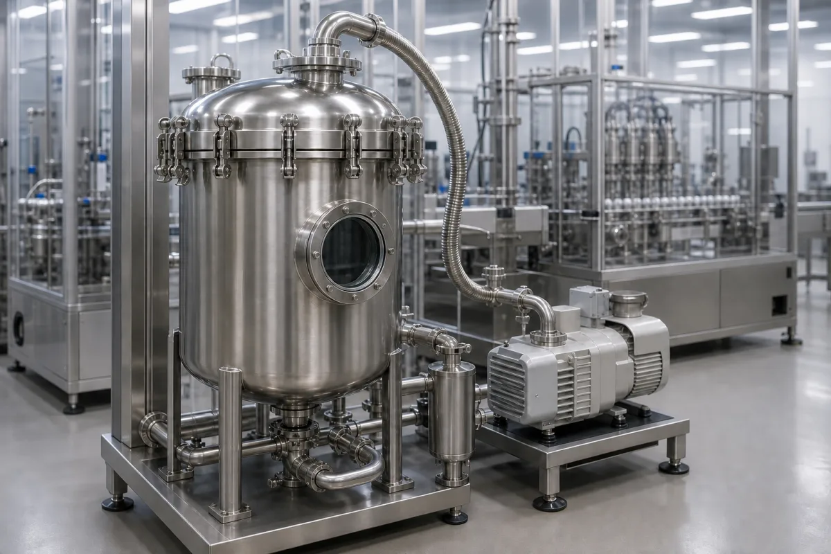
Vacuum Degassing Chamber in a manufacturing environment
Representative product image. Confirm appearance and specifications with the manufacturer.

Product Specifications

Technical details and manufacturing context for Vacuum Degassing Chamber

Definition
The Vacuum Degassing Chamber is a component used in electrolyte filling systems within electrical equipment manufacturing. Its primary function is to remove dissolved gases—such as oxygen, nitrogen, and carbon dioxide—from liquid electrolytes. By creating a controlled vacuum environment, the chamber reduces the partial pressure of gases above the liquid, causing them to come out of solution as bubbles, which are then evacuated. This process is essential for preventing gas bubbles from interfering with subsequent filling operations, ensuring consistent electrolyte properties, and improving the performance and longevity of the final electrochemical cells or batteries.

The chamber is typically constructed from stainless steel (e.g., 316L) with a borosilicate glass viewport and fluoropolymer seals (e.g., PTFE, Viton). It is designed to operate within specific parameters, including a chamber volume of 50–500 liters, an ultimate vacuum of 0.1–1.0 Pa, a leak rate of ≤1×10⁻⁹ Pa·m³/s (per ISO 21360), and an operating temperature range of 10–60°C. The maximum allowable pressure for testing is 0.5 MPa (per GB 150). Power supply is three-phase 220/380 V AC, with power consumption ranging from 2.2 to 7.5 kW depending on the vacuum pump size. Ingress protection is rated IP54–IP65 (per IEC 60529). Chamber material options include 304 or 316L stainless steel (per ASTM A240), and the weight ranges from 300 to 1500 kg, which should be considered in floor loading calculations.

These parameters are reference ranges and must be verified with the manufacturer for the specific model and application. The chamber is not a standalone product; it is integrated into a larger electrolyte filling system. Proper selection requires consideration of batch size, required vacuum level, and compatibility with the electrolyte chemistry. Maintenance signals include increased leak rate, visible seal degradation, or reduced vacuum performance. Failure boundaries include exceeding the operating temperature range, which may damage seals, or exceeding the maximum allowable pressure, which could compromise structural integrity. Always consult the supplier for model-specific specifications and compliance with applicable standards.
Working Principle
The chamber is sealed and connected to a vacuum pump. When the vacuum is applied, the pressure inside the chamber drops significantly below atmospheric pressure. This reduction in pressure lowers the solubility of gases in the electrolyte, causing them to nucleate and form bubbles. These bubbles rise to the surface of the liquid and are removed from the chamber by the vacuum system. The process may involve agitation or controlled temperature to enhance degassing efficiency.
Common Materials
Stainless Steel (e.g., 316L), Borosilicate Glass Viewport, Fluoropolymer Seals (e.g., PTFE, Viton)
Technical Parameters
ParameterTypical rangeNotes & selection driver
Chamber Volume50–500 LSelect based on batch size
Ultimate Vacuum0.1–1.0 PaLower pressure improves degassing efficiency
Leak Rate≤1×10⁻⁹ Pa·m³/sCritical for maintaining vacuumISO 21360
Operating Temperature10–60 °CExceeding range may damage seals
Max Allowable Pressure0.5 MPaFor pressure testing onlyGB 150
Power Supply220/380 V ACThree-phase for industrial use
Power Consumption2.2–7.5 kWDepends on vacuum pump size
Ingress ProtectionIP54–IP65Higher rating for dusty environmentsIEC 60529
Chamber Material304/316L SS316L for corrosive electrolytesASTM A240
Weight300–1500 kgInclude in floor loading calculations

Ranges are indicative industry figures for RFQ preparation, not a supplier commitment. Confirm every value and standard with the legal manufacturer before ordering.

Components / BOM
  • Chamber Body Part
    Provides the main sealed volume to hold the electrolyte under vacuum.
    Material: Stainless Steel
  • Vacuum Port Part
    Connection point for the vacuum pump or system.
    Material: Stainless Steel
  • Viewport
    Allows visual inspection of the degassing process and liquid level.
    Material: Borosilicate Glass
  • Sealing Gasket Part
    Ensures a vacuum-tight seal on access doors or ports.
    Material: Fluoropolymer (e.g., Viton)
  • Agitation System Optional
    Stirs the liquid so trapped bubbles reach the surface faster.
  • Temperature Control Optional
    Warms the electrolyte to lower gas solubility and speed up degassing.

Applied To / Applications

This component is essential for the following industrial systems and equipment:

Industrial Ecosystem & Supply Chain Structure

Complementary Systems
Downstream Applications
Specialized Tooling

Application Fit & Sizing Matrix

Operational Limits
pressure: Full vacuum to 1.5 bar absolute (max operating pressure)
flow rate: Up to 50 m³/h (depending on chamber size)
temperature: 5°C to 80°C (operating range)
slurry concentration: Up to 40% solids by weight (non-abrasive)
Media Compatibility
✓ Electrolyte solutions for electroplating ✓ Pharmaceutical process liquids ✓ Deionized water systems
Unsuitable: Hydrofluoric acid or highly corrosive halogenated compounds
Sizing Data Required
  • Required degassing efficiency (e.g., target dissolved oxygen level)
  • Process flow rate (m³/h)
  • Initial gas concentration in solution

Reliability & Engineering Risk Analysis

Failure Mode & Root Cause
Vacuum Seal Degradation
Cause: Thermal cycling and chemical exposure causing elastomer seals to harden, crack, or lose elasticity, leading to vacuum leaks.
Corrosion and Pitting
Cause: Exposure to aggressive process gases, moisture ingress, or improper cleaning agents attacking chamber walls and internal components.
Maintenance Indicators
  • Gradual increase in base pressure or inability to reach target vacuum levels during operation
  • Unusual audible hissing or whistling sounds during pump-down cycles indicating vacuum leaks
Engineering Tips
  • Implement regular helium leak testing with mass spectrometry to detect and locate micro-leaks before they become critical failures
  • Establish strict moisture control protocols including nitrogen purging after maintenance and using desiccant breathers on vent ports to prevent internal corrosion

Indicative industry ranges for design and RFQ preparation. Confirm the exact figures and applicable standard with the manufacturer before specifying.

Compliance & Manufacturing Standards

Applicable Standards
ANSI/ASME B31.3 - Process piping CE marking - Pressure Equipment Directive 2014/68/EU

Quoted from the published standard.

Manufacturing Precision
  • Vacuum seal surface flatness: ≤0.1mm
  • Chamber wall thickness tolerance: ±0.5mm
Quality Inspection
  • Helium leak test (vacuum integrity)
  • Pressure test (hydrostatic/pneumatic)

Manufacturers of Vacuum Degassing Chamber

1 company lists this product among what they make. Company figures are quoted from each company's own website; every card states where the relationship came from.

ShenZhen TROY Intelligent Robotics Co.,Ltd.
Shenzhen, Guangdong, CN
Listed on the company's own website · profile compiled by CNFX from public sources
Listed there as: “vacuum degassing chambers”
View source page ↗ troysupply.com · checked 2026-09-10

Manufacturer listings support early research and capability understanding. They are not certification, ranking, or transaction guarantees.

Share this page
Technical documentation
Request current drawings, revision history, and a signed specification sheet.
Manufacturing capability
Verify equipment lists, process limits, capacity, and representative production evidence.
Inspection readiness
Confirm test methods, calibrated equipment, sampling plans, and traceable reports.
Supplier transparency
Check the legal entity, factory address, ownership, certifications, and direct contacts.

CNFX does not score or rank suppliers. Buyers must verify all claims and documents with the legal manufacturer before ordering.

Supply Chain Compatible Machinery & Devices

Medium Voltage Switchgear Assembly Line

Automated production system for assembling medium voltage electrical switchgear.

Explore Specs →
Motor Terminal Block

A motor terminal block is a standardized electrical component that provides secure, insulated connection points for motor winding leads.

Explore Specs →
PLC Control System

A digital industrial computer control system that monitors inputs, makes decisions based on a custom program, and controls outputs to automate industrial processes.

Explore Specs →
Control Panel

A centralized interface for monitoring and controlling industrial equipment and processes

Explore Specs →

Frequently Asked Questions

What is the purpose of a vacuum degassing chamber in electrolyte filling?

It removes dissolved gases from liquid electrolytes to prevent gas bubbles from interfering with filling operations, ensuring consistent electrolyte properties and improving the performance and longevity of electrochemical cells.

What materials are commonly used for the chamber?

Typical materials include stainless steel (e.g., 316L) for the chamber body, borosilicate glass for viewports, and fluoropolymer seals (e.g., PTFE, Viton) for vacuum integrity.

What are the key parameters to consider when selecting a vacuum degassing chamber?

Key parameters include chamber volume (50–500 L), ultimate vacuum (0.1–1.0 Pa), leak rate (≤1×10⁻⁹ Pa·m³/s per ISO 21360), operating temperature (10–60°C), and ingress protection (IP54–IP65). These must be verified for the specific model.

How should maintenance and failure be monitored?

Monitor for increased leak rate, visible seal degradation, or reduced vacuum performance. Avoid exceeding the operating temperature range (10–60°C) to prevent seal damage, and do not exceed the maximum allowable pressure (0.5 MPa) for testing.

Data Basis

Editorial classification, named public sources where available, and source-reviewed manufacturer records.

Preliminary Technical Classification
This page supports structured research, RFQ preparation, and supplier evaluation. It does not replace buyer-led supplier qualification, standards review, or technical approval.
Buyer enquiry

Request manufacturing insight for Vacuum Degassing Chamber

Ask for use case, specification boundaries, supplier type, and RFQ preparation information for this product.

Where it goes
Straight to the CNFX editorial desk, and to the manufacturer if this product is linked to a claimed profile. Nothing is broadcast to a supplier list.
Your details stay here
We do not sell or rent enquiry data, and we do not add you to a mailing list. Used only to answer this request.
No commission, no middleman
CNFX is a directory. We take no cut of any order and never negotiate on a supplier's behalf.
What we don't claim
A listing is not an endorsement. Qualify every supplier and verify every figure yourself before ordering.

Your business information is used only to process this request.

Thank you! Your message has been sent. We'll respond within 1–3 business days.
Sorry, we couldn't send your message. Please try again, or email us at [email protected].

Need to Manufacture Vacuum Degassing Chamber?

Compare manufacturer profiles with relevant product and process capability.

Previous Product
Wire Tensioning System
Last Product
Get QuotesChat