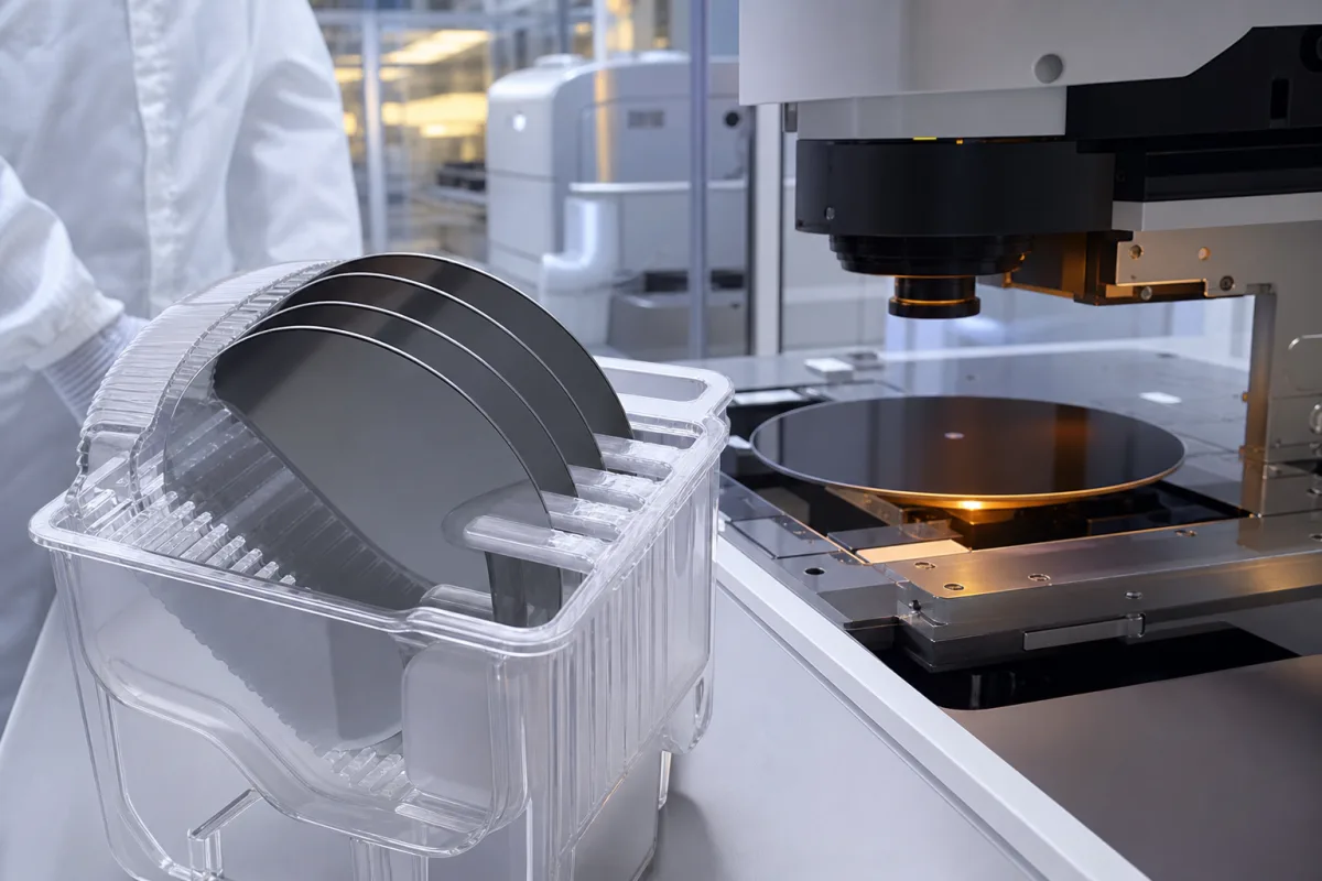
GaAs substrates · Semi-insulating versus conducting types and dopants, VGF versus LEC growth and etch pit density, diameter and thickness
A gallium arsenide (GaAs) wafer substrate is a thin polished slice of single-crystal GaAs on which epitaxial layers are grown for RF transistors, LEDs, lasers and solar cells. Ask three things first: whether you need semi-insulating or conducting (n- or p-type) material and with which dopant, which growth method and etch pit density the device needs, and what diameter, thickness and flat or notch orientation your fab line uses.
Single-crystal GaAs substrates, semi-insulating and doped, 2 in to 200 mm, epi-ready polished. GaAs epitaxial wafers with device layers, InP, GaN, SiC and silicon wafers are outside this page.
CNFX editorial research · Sources checked October 12, 2026 · 5 sources
Freiberger Compound Materials explains that its GaAs, InP and GaN wafers are cut from crystals grown from the melt by LEC or VGF (or from the gas phase by HVPE), with dopants giving n- or p-type high-resistance (>10⁷ Ω·cm) or low-resistance (<10⁻² Ω·cm) material, and that wafer surfaces are epi-ready. [1]
Its GaAs specification table pairs type and application: semi-insulating (undoped or carbon) VGF wafers for HBT, pHEMT and solar; silicon-doped n-type VGF wafers for LEDs, high-brightness LEDs, solar and detectors, with tighter-EPD Si-doped grades for lasers; zinc-doped p-type VGF wafers for LEDs and solar; LEC semi-insulating wafers for pHEMT and MESFET; and Te-doped LEC n-type wafers for LEDs. Listed thicknesses are 675 µm at 150 and 200 mm and 625 or 450 µm at 100 mm. [1] A linked supplier offers 2, 3, 4 and 6 in VGF/LEC wafers in undoped and Cr-doped semi-insulating, Si- and Te-doped n-type and Zn-doped p-type versions. [3]
Editorial note: semi-insulating substrates isolate RF devices built on top; conducting substrates carry current through the back for LEDs and lasers. Specify both the type and the dopant, since Si and Te n-type grades differ in growth method and EPD in Freiberger's table.
Give the supplier the device type, conduction type and dopant, resistivity or carrier concentration range, EPD limit, growth method preference, diameter, thickness and tolerance, flat or notch, orientation and off-cut, polish (single or double side), flatness, bow and warp, surface and particle limits, epi-ready packaging and quantities.
02
Set etch pit density and growth method
Freiberger's table lists etch pit density limits that depend on type, diameter and growth method: semi-insulating VGF wafers at ≤12,000 (200 mm), ≤10,000 (150 mm) and ≤7,500 (100 mm); Si-doped VGF wafers at ≤3,000 for LEDs and ≤50 (150 mm) or ≤100 (100 mm) for lasers; Zn-doped VGF at ≤3,000–5,000; and LEC semi-insulating and Te-doped wafers at ≤100,000. [1]
Freiberger has said that LEC is the more economical process while VGF wafers have characteristics such as lower etch pit density, which can be an advantage in some applications, that it offered both methods, and that it produced the first 200 mm semi-insulating GaAs wafers from VGF crystals under R&D conditions, with larger diameters allowing fabs to use 200 mm silicon equipment. [2]
Editorial calculation: if the EPD limits are per cm² — the usual unit — a 150 mm wafer (about 177 cm²) at ≤10,000 could carry up to about 1.8 million etch pits, while a laser-grade ≤50 wafer would carry no more than about 8,800. Confirm the unit and measurement method on the supplier's certificate. [1]
03
Specify orientation accuracy, off-cut and special wafer forms
IQE's GaAs substrate page lists VGF-grown wafers supplied as cut, etched or polished, with an epi-ready finish checked in house by Surfscan haze and particle monitoring, spectroscopic ellipsometry and grazing-incidence interferometry, and an orientation precision of ±0.05°, or ±0.02° in a high-accuracy option measured by triple-axis X-ray diffractometry. Its special-options page adds precise misorientation in any direction from the growth plane, cleaved flats, high-index orientations such as (x,1,1) with x from 1 to 6 and (110), low-cost non-epi-ready process trial wafers for reactor set-up and etch experiments, and ultra-thin 2-inch and 3-inch GaAs wafers as thin as 150 µm for laser facet coating and spacer uses, which are not finished to full epi-ready standard. Wafers ship in coin-style trays, cassettes or custom packs. [4][5]
Editorial calculation: ±0.05° is ±3 arcminutes and ±0.02° is ±1.2 arcminutes; a 150 µm wafer is about a quarter of the 625 µm thickness Freiberger gives as one standard example. On the order, state the nominal orientation, the off-cut angle and its direction and tolerance, the flat or notch, and whether trial wafers may be non-epi-ready, since these change price and epitaxial results. [4][5][1]
Suppliers linked to this page list GaAs wafers; each card links to the page reviewed.
The listing reviewed offers 2–6 in GaAs wafers by VGF or LEC in five doping types alongside other crystal wafers; ask for the crystal grower, EPD map and resistivity data.
05
Trace what the wafer specification controls
This is a functional reference built from the sources cited; it is not one maker's specification.
Fill the specification fields with values for your parts
A GaAs wafer quotation needs values for your devices. The table explains each field, gives published values where a reviewed source states them, and says what to obtain from the supplier.
Explore company information and manufacturing capabilities, then discuss the scope of your project with a relevant supplier.
Share this page
Compiled and source-reviewed by the CNFX editorial team.
Published product pages show what a company offers, not tested performance. Confirm the legal seller, crystal grower and scope for your order. How we source and review
· Page last updated 13 October 2026
Buyer questions
What is the difference between VGF and LEC GaAs?
Freiberger says LEC is more economical, while VGF wafers have lower etch pit density. [2]
What EPD do GaAs laser substrates need?
Freiberger lists Si-doped VGF laser-grade wafers at EPD ≤50 (150 mm) or ≤100 (100 mm). [1]
What resistivity is semi-insulating GaAs?
Freiberger describes high-resistance material as above 10⁷ Ω·cm. [1]
What sizes of GaAs wafers are available?
Freiberger lists 3 in to 200 mm; a linked supplier offers 2–6 in. [1][3]
How accurately can GaAs wafer orientation be specified?
One substrate maker lists ±0.05° as standard and ±0.02° as a high-accuracy option measured by triple-axis X-ray diffractometry. [4][5]
Sources and what still needs a direct check
Sources checked 2026-10-12. Freiberger Compound Materials is a GaAs crystal and wafer maker publishing its specification table; Compound Semiconductor reported its statements on VGF and LEC; OST Photonics is a linked supplier.