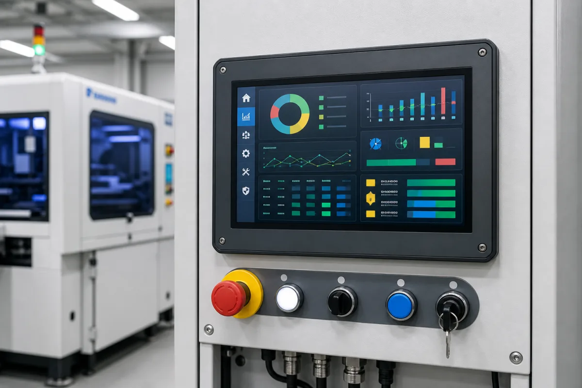
HMI interface operator station: touch panel, emergency stop and pushbuttons in a machine-side operating housing
Machine-side HMI operator stations · Touch panel plus emergency stop and pushbuttons in an operating housing, support-arm load and length limits, and the latching emergency stop device standard
This page covers the operator station where a person meets the machine: an operating housing that carries the HMI touch panel together with the emergency stop, illuminated pushbuttons, selector and key switches, mounted on the machine, a pedestal or a support arm and wired back to the control cabinet. Ask three things first: what the housing and its components weigh and how far the arm must reach, which emergency stop device and other control devices are fitted, and how cables, potential equalisation and protection are handled through the arm.
Operator stations and operating housings that combine an HMI touch panel with emergency stop, pushbuttons and switches, including support-arm and pedestal mountings. Operator touch panels and text panels on their own are covered on the Human machine interface page. General-purpose industrial PCs, explosion-proof panel PCs and remote pendants are outside this page.
CNFX editorial research · Sources checked October 12, 2026 · 3 sources
Rittal's technical catalogue for its CP 60/120/180 support arm systems describes one system with three combinable cross-sections, stable for all load levels up to 1,800 N (180 kg), with continuous automatic potential equalisation, integrated cable and edge protection, adjustable rotation limits and an open support section for upgrades and servicing; in the vertical axis a change to the next smaller system is possible without impairing load capacity. The permissible static load covers the housing and the vertical support arm section and falls as jib length grows. [1]
The same catalogue gives a maximum jib length B of 2,000 mm for the CP 60 system, with or without an intermediate hinge, and for the CP 120 a maximum system length of 2,500 mm with a horizontal outlet at the start of the system and 1,500 mm with a vertical outlet. For small and slimline operating housings it lists the CP 40 round-tube system for loads up to 400 N, and it names Comfort Panel, Optipanel, operating housings with handle strips and housings for desktop TFTs as matching housings, with a support arm configurator that uses jib length, housing weight and cable cross-sections to select the system. [1][2]
Editorial calculation: 1,800 N is about 183 kg under standard gravity (1,800 ÷ 9.81), which Rittal rounds to 180 kg; a 25 kg housing with panel and devices exerts about 245 N, well inside the 400 N of a CP 40, but the arm's rating at your jib length on Rittal's chart is what decides the system. [1]
Give the supplier the panel size and weight, the list of control devices, the housing material and protection rating you need, the reach and height of the arm or pedestal, rotation range, and the number and cross-section of cables to route.
02
Fit the emergency stop and other control devices
IEC 60947-5-5:2026, published on 18 February 2026 as the second edition, gives detailed specifications for the electrical and mechanical construction and testing of emergency stop devices with mechanical latching function used to initiate an emergency stop signal; it does not apply to hydraulic or pneumatic emergency stop devices or to devices without mechanical latching, and it refers to IEC 60204-1:2016 and its 2021 amendment, 9.2.3.4. [3]
The 2026 edition reshapes clause numbering to match the rest of the IEC 60947 series, revises the test method for the latch mechanism, and adds Annex B with requirements for illuminated push-button emergency stop devices, including distinguishing "active and inactive" by changing the colour of the push-button with the illumination. An emergency stop device conforming to it can also form part of an emergency switching-off means under IEC 60364-5-53. [3]
Editorial note: ask the supplier which edition the emergency stop device is certified to, whether an illuminated device to Annex B is fitted, and how the emergency stop circuit is wired from the operating housing to the safety controller in the cabinet.
03
CP support arm sizes against machine-mounted operating housings
The mounting decides reach, load and cable routing.
Explore company information and manufacturing capabilities, then discuss the scope of your project with a relevant supplier.
Share this page
Compiled and source-reviewed by the CNFX editorial team.
Each manufacturer above links to the page on that company's own website where the product is listed, with the date we checked it. How we source and review
· Page last updated 13 October 2026
Buyer questions
How much can a support arm carry?
Rittal rates its CP 60/120/180 systems up to 1,800 N (180 kg), falling with jib length, and its CP 40 round-tube system up to 400 N. [1]
Which standard covers emergency stop devices on an operator station?
IEC 60947-5-5:2026 covers electrical emergency stop devices with mechanical latching function, including a new Annex B for illuminated push-button types. [3]
How long can a support arm be?
Rittal gives up to 2,000 mm jib length for CP 60 and up to 2,500 mm system length for CP 120 with a horizontal outlet. [1]
Sources and what still needs a direct check
Sources checked 2026-10-12. Rittal describes its own support arm systems; the IEC 60947-5-5 scope and changes are quoted from the Standard Norge catalogue listing.