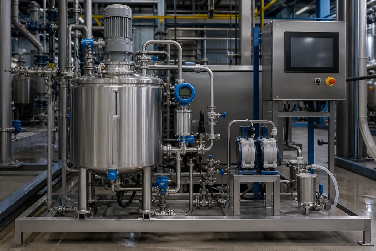
Automatic viscosity controllers for solvent-thinned adhesives, paints and inks · Stirred solution tank, viscometer placement, shielding from stirring flow, solvent tank and dosing valve, inline sensors, and why manual cup checks drift
An automatic viscosity control system keeps a solvent-thinned liquid such as an adhesive, paint or printing ink at its set viscosity while it is being used: the liquid is stirred, a viscometer measures it, and a controller adds solvent to replace what evaporates. Ask three things first: what liquid and solvent you are controlling and at what set viscosity, where and how the viscosity will be measured without disturbance from stirring or flow, and how solvent is metered and the control proven.
Closed-loop viscosity control units that measure the viscosity of a stirred tank or circulating line and dose solvent (or diluent) automatically, including the tank and stirrer, viscometer, solvent supply, dosing valve and controller. Laboratory viscometers, batch mixers without viscosity control, and dosing of reactive components are outside this page except where compared.
CNFX editorial research · Sources checked October 12, 2026 · 4 sources
Japanese patent application JP H03-192408 A (Automatic viscosity controller; English text from the Google Patents machine translation) concerns adhesives, paints and similar solutions used diluted with a volatile solvent. Its example is an adhesive thinned with toluene for bonding anti-vibration rubber to metal parts: because the solvent evaporates, viscosity rises over time. It explains that when an operator reads a tank viscometer and adds solvent by hand, measurement errors, forgotten or wrong additions leave viscosity varying by about 10%, giving uneven coating if too thick and sagging or lower bond strength if too thin, and that flow from the tank stirrer can disturb the viscometer reading. [1]
The device it describes stirs the solution with a motor-driven screw, measures viscosity with a rotational viscometer in a protective tube open at the bottom with communication windows, and places a plate-shaped or curved shielding member between the stirrer and the viscometer so the stirring flow does not reach it directly. [1]
US patent 5,677,481 (Viscosity maintenance) notes that the desired ink viscosity in a gravure press depends on substrate, printing speed and ink type, and that viscosity is affected by solvent evaporation and ambient temperature. Its reservoir stirrer has a rigid and a flexible paddle, so it both mixes the ink and, by the time lapse between the two paddles passing sensors, gives a value related to viscosity. [2]
An inline viscometer maker describes its ink system as a sensor placed directly in the ink line, a pneumatic solvent correction valve fed from a central solvent tank to each ink bucket, and a controller; it states that "many of these systems, once purchased, were taken out of service by operators, who went back to using efflux cups to measure viscosity". [3]
Give the supplier the liquid and solvent, solids content, set viscosity and tolerance, temperature range, tank volume or line flow, stirrer type and speed, measuring method (rotational, vibrational, flow time) and sensor location, cleaning between jobs, solvent supply and hazardous-area classification, materials in contact, and how readings will be checked against your reference cup or laboratory viscometer.
02
Dose solvent and prove the control
In JP H03-192408 A, a solvent tank stores the solvent airtight, a transport pipe with a regulating valve connects it to the solution tank, and a controller drives the valve from the viscometer reading so the solution stays at the set viscosity. [1] In US 5,677,481 a solvent reservoir with a flow controller (a pump or solenoid) feeds the ink reservoir, a cover limits evaporation, and the controller adds solvent according to the measured time lapse. [2]
Editorial note: ask the supplier to show, on your liquid, how far viscosity drifts between corrections, how a solvent valve failure or empty solvent tank is detected, and how temperature is compensated, since the US patent names ambient temperature as one of the factors that changes ink viscosity.
03
Choose the inline sensor version for pressure, hygiene and low viscosity
Sofraser's product page for its MIVI process viscometer describes a vibrating-needle sensor inserted directly into the process, which can be mounted in line, on a reactor or in a flow cell, and which also reports density. It offers versions that can be combined. The sanitary version has no dead spaces, is cleaned in place without removal and is made in corrosion-resistant 316L stainless steel; Sofraser notes it is for cases where a fully EHEDG-certified design is not required. The high-pressure version is rated to 450 bar as standard and up to 1,500 bar as an option, for drilling, spray dryers and injection. The high-sensitivity version resolves down to 0.0001 cP for very low-viscosity liquids such as light fuels, solvents, dilute solutions and low-viscosity starch solutions used in paper, packaging and food. [4]
Editorial calculation: 450 bar is 45 MPa and 1,500 bar is 150 MPa; 0.0001 cP is 0.0001 mPa·s, about one ten-thousandth of the viscosity of water at room temperature. For a solvent-thinned ink or adhesive loop, ask which version matches your line pressure and cleaning regime, and ask the supplier to demonstrate the sensor's reading against your laboratory viscometer on your own liquid before setting the control band. [4][3]
Tank, stirrer, shielded viscometer, solvent tank, dosing valve and controller
JP H03-192408 A puts a shielding member between the stirrer and the viscometer so the stirring flow does not upset the reading; Rheonics instead places its sensor directly in the ink line. [1][3]
Viscosity range, control band, temperature and pressure rating for a viscosity controller
The one control figure in this table is the starting point: about 10% variation under manual checking in the Japanese patent's example, the band an automatic system has to beat on your liquid. [1]
Explore company information and manufacturing capabilities, then discuss the scope of your project with a relevant supplier.
Share this page
Compiled and source-reviewed by the CNFX editorial team.
Each manufacturer above links to the page on that company's own website where the product is listed, with the date we checked it. How we source and review
· Page last updated 13 October 2026
Buyer questions
Why does solvent-thinned adhesive or ink need viscosity control?
The volatile solvent evaporates and viscosity rises; manual checking and topping up left about 10% variation in one patent's example. [1]
Can a stirrer disturb a viscometer?
Yes; JP H03-192408 A places a shielding member between stirrer and viscometer so the stirring flow does not upset the reading. [1]
What sets the right ink viscosity on a gravure press?
US 5,677,481 says it depends on substrate, printing speed and ink type, and drifts with solvent evaporation and temperature. [2]
What pressure can an inline viscometer withstand?
One vibrating-needle process viscometer is rated to 450 bar as standard and up to 1,500 bar as an option; a high-sensitivity version resolves down to 0.0001 cP. [4]
Sources and what still needs a direct check
Sources checked 2026-10-12. Two patents describe devices in their own terms (the Japanese text is a machine translation); the Rheonics ink-system description and the Sofraser MIVI product page are sensor makers' own technical descriptions and state the makers' views.