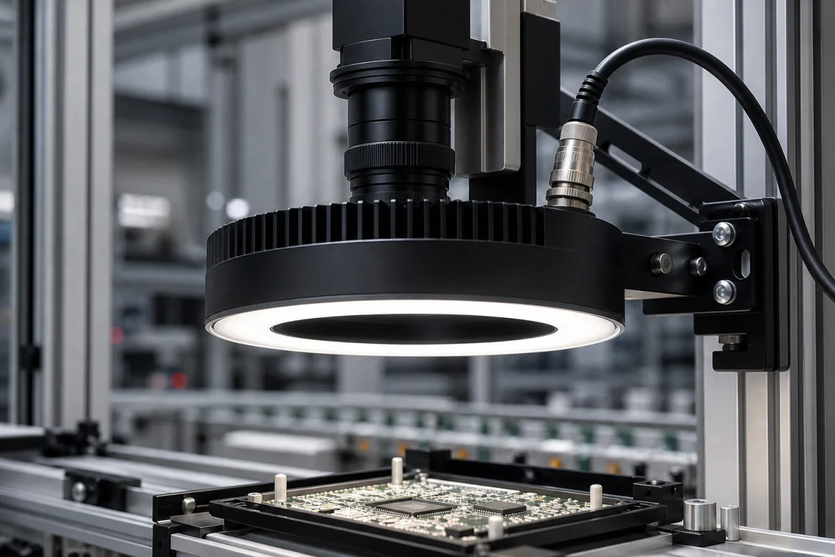
Illumination system (the projection lighting that lets a solder paste inspection camera measure deposit height and volume)
The light-projection system of 3D solder paste inspection · laser line triangulation versus Moiré fringe projection, the shadow effect behind a deposit, one projector or two, depth of field and board warpage, and phase-shift measurement at known intervals
A 3D solder paste inspection (SPI) camera does not see height directly: a projector throws a laser line or a pattern of fringes onto the board at an angle, and the camera measures how the pattern shifts over each deposit. The illumination system therefore decides how much of each deposit is measured, how well the machine copes with warped boards, and how fast it can scan. Specify the projection method, the number and direction of projectors, the depth of field, and the measurement resolution and repeatability it must achieve.
Projection and illumination systems of 3D solder paste inspection: laser-line triangulation, Moiré and phase-shift fringe projection, single and dual projectors, depth of field and warpage compensation. Machine vision LED lights and controllers are covered on the Machine vision illumination unit page; structured-light projectors for 3D scanning on the Structured light projector for 3D scanning page; stencil printers on the Solder paste printer page; post-placement and post-reflow AOI on the Automated optical inspection (AOI) system for PCB assembly page.
CNFX editorial research · Sources checked October 12, 2026 · 3 sources
Laser line or fringe projection, and the shadow effect
Jean-Marc Peallat of Vi Technology describes laser triangulation SPI as a laser trace whose deviation gives height, combined with a 2D image. Its drawbacks are "mainly linked to the lack of resolution leading to a poor accuracy", and with one laser "the exact value of the volume cannot be calculated": the single angled beam and the camera leave a blind spot on the far side of each deposit, the "Shadow effect", where paste is not counted. "The error in the measurement value varies from shape to shape but can be up to 48% in the case of round apertures", and laser profiling is also affected by PCB colour and finish. [1]
Moiré topography instead projects modulated interference fringes and measures height and volume by moving the observation grating; Peallat lists its drawbacks as limited depth of field "(more or less compensated by Z movement)", sensitivity to noise and vibration in the grating process, and cycle time. [1][2]
Method
How height is found
Limits given
Source
Laser triangulation
Deviation of a laser trace
Resolution; shadow effect up to 48% volume error on round apertures; PCB colour and finish
One projector or two, depth of field and warped boards
Peallat notes that "The MoirØ methodology is also subject to “shadow effect” if only one source of grating is used", and that "Often, most of the systems using MoirØ have 2 modes of operation": one source for speed at reduced accuracy, two sources for better accuracy at slower speed. Inspecting field of view by field of view with individual Z adjustment means "the references won’t be the same" across a BGA array, which can make height or volume readings differ. [1]
The scanning approach he describes, flying absolute height profilometry, scans the board with a top-down camera and "2 structured light sources (from each sides)", eliminating the shadow effect; with "a 6mm depth of field of view" it measures the board profile during the scan and compensates for warpage over the whole board, referencing height around each pad without Z adjustment. [1]
Give the smallest apertures and deposits, the board size, thickness and expected warpage, and the cycle time; ask whether the quoted accuracy is with one or two projectors.
03
Phase-shift measurement at known intervals
Chrys Shea, writing in Circuits Assembly, explains the stripes as a Moiré pattern and "the method of measuring them at known intervals" as phase shift interferometry: "By taking several measurements at known intervals, the height of the surfaces can be calculated mathematically." Koh Young's system divides each deposit "into tiny segments as small as 10 µm", measures their location and height, builds a 3D model and compares it with a theoretical one, with a gage R&R "of less than 10%" in the article. [3]
The article places the need where 0.5 mm area array devices arrived and inspection had to read 0.010-inch deposits accurately and fast enough for production. [3]
04
SPI illumination details
Paste it into your enquiry below or into an email to a maker, then replace every bracket.
Explore company information and manufacturing capabilities, then discuss the scope of your project with a relevant supplier.
Share this page
Compiled and source-reviewed by the CNFX editorial team.
Each manufacturer above links to the page on that company's own website where the product is listed, with the date we checked it. How we source and review
· Page last updated 13 October 2026
Buyer questions
What is the shadow effect in SPI?
A single angled light source leaves the far side of each deposit unseen, so that paste is not counted; Peallat gives volume errors up to 48% on round apertures with laser triangulation. [1]
Why use two projectors?
Fringes projected from both sides remove the shadow effect; single-source Moiré runs faster but less accurately. [1]
How does phase shift measure height?
Circuits Assembly describes "taking several measurements at known intervals" of the fringe pattern and calculating surface height. [3]
What about warped boards?
The scanning system Peallat describes has 6 mm depth of field and compensates warpage measured during the scan. [1]
Sources and what still needs a direct check
Sources checked 2026-10-12. SMTnet hosts Jean-Marc Peallat's Vi Technology paper on 3D SPI, also published by I-Connect007's SMT007; Circuits Assembly published Chrys Shea's article on phase shift interferometry.