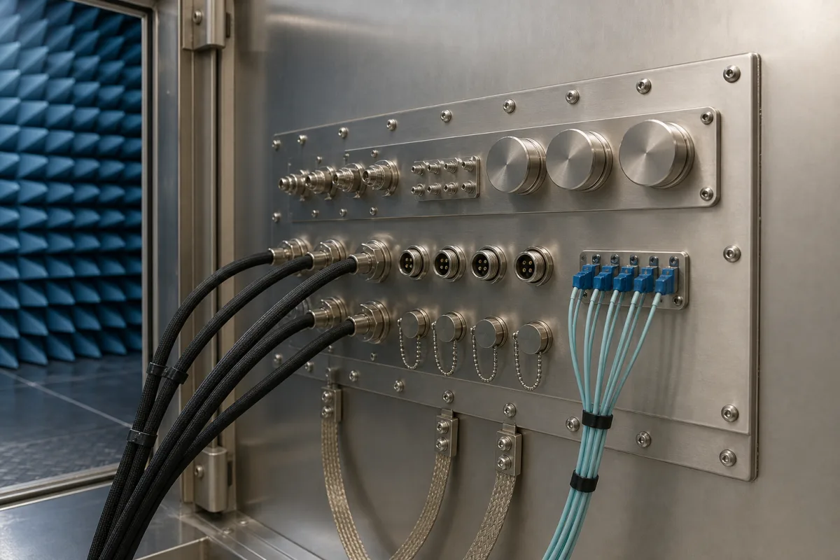
Every cable that enters a shielded room or EMC test chamber is a possible leak, so the connections are gathered on one bulkhead plate, the interface panel, mounted in the shield wall. It carries coaxial bulkhead connectors for antennas and instruments, filtered connectors for power and data, fibre-optic ports and, where needed, pipe penetrations. What to settle is which penetrations the room needs, how much each one lets through at your test frequencies, and how the plate is bonded to the shield.
Bulkhead interface panels (connector or feedthrough panels) for shielded rooms, EMC and anechoic chambers: the plate with its coaxial bulkhead connectors, filtered data feedthroughs, fibre-optic waveguide ports and waveguide pipe penetrations, with gasketing and bonding. Honeycomb air vents are covered on the Waveguide ventilation panel page, and complete demountable shielded rooms on the Modular shielded enclosure page. Operator front panels and membrane keypads are a different product and outside this page.
CNFX editorial research · Sources checked October 12, 2026 · 5 sources
Coaxial bulkheads and filtered D-sub feedthroughs on a brass plate
Raymond EMC states that integrating an RF connector or a filtered feedthrough into its shielded rooms requires a bulkhead connector panel to keep the room's shielding effectiveness. It builds these panels mainly in brass, in standard sizes of 12 × 12, 18 × 12 and 18 × 18 in, machines custom hole patterns, and installs them on site to measurements taken after the shield is erected. [1]
For data lines Raymond supplies D-subminiature filtered feedthroughs and publishes their insertion loss by filter capacitance; it notes that fitting one may reduce the room's overall shielding effectiveness to the levels in the table, depending on cable length and jacket shield type inside and outside the room. [2]
Filter
3 dB cutoff
100 MHz
500 MHz
1 GHz
2 GHz
5 GHz
J, 100 pF
32 MHz
6 dB
27 dB
40 dB
43 dB
40 dB
A, 310 pF
17 MHz
13 dB
36 dB
43 dB
50 dB
45 dB
C, 1000 pF
3.2 MHz
30 dB
62 dB
70 dB
68 dB
63 dB
For each penetration give the panel maker the connector type and gender on each side, signal or power rating, frequency range, filter attenuation needed, fibre connector type and count, pipe sizes and media, panel size and location in the wall, and the shielding effectiveness the room must still meet after the panel is fitted.
02
Fibre-optic ports: all-metal adapters versus waveguide bores
Masterson and Novotny of NIST tested optical-fibre bulkhead adapter feedthroughs from 1 to 16 GHz to see how much they degraded an enclosure's shielding effectiveness; results ranged from about 20 dB for polymer adapters to nearly 90 dB for an all-metal FC connector system. [3]
ETS-Lindgren's fibre-optic waveguide filter takes a different route: a removable centre plug accepts ST or SMA connectors, and the connectorised cables pass through six or twelve waveguide bores around it, with all connectors installable while keeping 100 dB attenuation at 18 GHz. [4]
Editorial calculation: at each frequency ETS-Lindgren lists, the 12-bore version is 2.99–3.00 dB below the 6-bore version, matching 10·log₁₀(2) = 3.01 dB for doubling the number of identical apertures. Both fall steeply above 18 GHz, so check the table against the highest frequency the chamber is used at. [4]
Frequency
WGF-6 theoretical attenuation
WGF-12 theoretical attenuation
0.1 GHz
179.02 dB
176.02 dB
10 GHz
165.77 dB
162.78 dB
15 GHz
147.63 dB
144.63 dB
18 GHz
131.59 dB
128.59 dB
25 GHz
63.32 dB
60.32 dB
03
Pipe penetrations sized by waveguide cutoff
Raymond EMC's bulkhead panels also carry waveguide pipe penetrations. [1] ETS-Lindgren's waveguide feed-throughs for water, gas, air and fire-suppression lines list the cutoff frequency for each nominal bore and give the circular-waveguide formula fc = c / 3.412r, with c = 1.181 × 10¹⁰ in/s and r the radius in inches, plus the rule that the waveguide length should be at least four times the diameter. [5]
Editorial calculation: for the 0.5 in bore, r = 0.25 in and fc = 1.181 × 10¹⁰ ÷ (3.412 × 0.25) = 13.8 GHz, matching the table; its 6 in length is 12 times the 0.5 in diameter, above the four-times rule. ETS-Lindgren offers dielectric unions for ground isolation and honeycomb inserts for higher-frequency or gas applications. [5]
Nominal I.D.
Cutoff
Length
Installation hole
1.27 cm (0.5 in)
13.8 GHz
15.24 cm (6 in)
2.22 cm (0.875 in)
2.54 cm (1 in)
6.9 GHz
15.24 cm (6 in)
3.49 cm (1.375 in)
3.81 cm (1.5 in)
4.6 GHz
15.24 cm (6 in)
4.92 cm (1.9375 in)
7.62 cm (3 in)
2.3 GHz
30.48 cm (12 in)
9.21 cm (3.625 in)
04
Interface panel penetration list
Paste it into your enquiry below or into an email to a maker, then replace every bracket.
Room: [shielded room or chamber type; wall material; required shielding effectiveness and frequency range]
RF: [connector types; count; frequency range]
Data and power: [filtered D-sub or other; filter capacitance; current and voltage]
Fibre: [connector type; count; adapter or waveguide port]
Pipes: [bore; medium; dielectric union; honeycomb insert]
Panel: [size; material; location; field installation]
Explore company information and manufacturing capabilities, then discuss the scope of your project with a relevant supplier.
Share this page
Compiled and source-reviewed by the CNFX editorial team.
Each manufacturer above links to the page on that company's own website where the product is listed, with the date we checked it. How we source and review
· Page last updated 13 October 2026
Buyer questions
What does an interface panel on a shielded room do?
It is the bulkhead plate through which RF connectors, filtered feedthroughs and pipe penetrations pass without degrading the shield; Raymond EMC builds them mainly in brass, 12 × 12 to 18 × 18 in. [1]
How much do filtered D-sub feedthroughs attenuate?
Raymond EMC shows 40 dB at 1 GHz for a 100 pF filter and 70 dB at 1 GHz for a 1000 pF filter. [2]
Do fibre-optic adapters leak RF?
NIST measured from about 20 dB for polymer adapters to nearly 90 dB for an all-metal FC system between 1 and 16 GHz. [3]
How long must a pipe penetration be?
ETS-Lindgren's rule of thumb is at least four times the waveguide diameter; its 0.5 in feed-through is 6 in long with 13.8 GHz cutoff. [5]
Sources and what still needs a direct check
Sources checked 2026-10-12. Raymond EMC and ETS-Lindgren publish data for their own shielded-room panels and feed-throughs; the NIST paper reports measurements of fibre-optic bulkhead adapters.