Editorial Technical Reference

Isolation/Communication Interface

This page explains how Isolation/Communication Interface is classified within Computer, Electronic and Optical Product Manufacturing. Technical values and manufacturer relationships are research references; confirm the current specification and supplier evidence for each order.

Technical Definition & Core Assembly

A specialized interface component within a Cell Monitoring Unit (CMU) that provides electrical isolation while enabling communication between battery cells and the monitoring system.
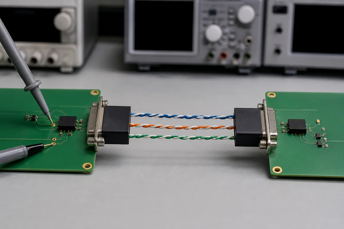
Isolation/Communication Interface in a manufacturing environment
Representative product image. Confirm appearance and specifications with the manufacturer.

Product Specifications

Technical details and manufacturing context for Isolation/Communication Interface

Definition
The Isolation/Communication Interface is a critical component of the Cell Monitoring Unit (CMU) in battery management systems. It serves two primary functions: providing galvanic isolation between high-voltage battery cells and low-voltage monitoring circuits to ensure safety, and facilitating bidirectional communication for transmitting cell voltage, temperature, and status data to the central battery management controller while receiving control commands. The interface typically employs optocouplers, capacitive isolation, or transformer-based isolation to create a barrier that prevents direct electrical connection while allowing signal transmission. Communication protocols such as CAN, SPI, or proprietary serial interfaces are implemented to exchange data between isolated domains. The component converts analog cell measurements to digital signals, transmits them across the isolation barrier, and may include error checking and fault detection mechanisms. Key parameters include an isolation voltage of 2500 V DC (per IEC 60747-5-5), data rates of 1–10 Mbps supporting CAN and SPI, an operating temperature range listed as -40 to 85 °C and requiring model-specific confirmation, and a supply voltage of 3.3–5.5 V DC. It also features common-mode transient immunity of 25–100 kV/µs, propagation delay of 10–60 ns, creepage distance of 8–12 mm and clearance distance of 6–10 mm (per IEC 60664-1), package size of 5–10 mm², weight of 0.5–2 g, humidity range of 5–95% RH (per IEC 60068-2-78), and ESD protection of ±8 kV (per IEC 61000-4-2). Materials include silicon semiconductor, epoxy resin encapsulation, copper conductors, and ferrite core for transformer isolation. These values are directory references and must be verified with the manufacturer for specific models and applications.
Working Principle
The interface uses isolation technology such as optocouplers, capacitive coupling, or transformers to create a galvanic barrier. Analog signals from battery cells are digitized, then transmitted across the barrier using protocols like CAN or SPI. The isolation prevents dangerous current flow while allowing data exchange. Error checking and fault detection may be integrated to ensure reliable communication.
Common Materials
Silicon semiconductor, Epoxy resin encapsulation, Copper conductors, Ferrite core (for transformer isolation)
Technical Parameters
ParameterTypical rangeNotes & selection driver
Isolation Voltage2500 V DCMinimum isolation rating between battery and communication linesIEC 60747-5-5
Data Rate1–10 MbpsSupports CAN and SPI communication protocols
Operating Temperature-40–85 °CExtended range for automotive battery environments
Supply Voltage3.3–5.5 V DCCompatible with typical CMU power rails
Common-Mode Transient Immunity25–100 kV/µsResists noise from switching convertersIEC 60747-5-5
Propagation Delay10–60 nsLow latency for real-time monitoring
Creepage Distance8–12 mmEnsures safety under pollution degree 2IEC 60664-1
Clearance Distance6–10 mmPrevents arcing at high voltageIEC 60664-1
Package Size5–10 mm²Compact footprint for PCB integration
Weight0.5–2 gLightweight for vibration resistance
Humidity Range5–95 % RHNon-condensing operating environmentIEC 60068-2-78
ESD Protection±8 kVContact discharge ratingIEC 61000-4-2

Ranges are indicative industry figures for RFQ preparation, not a supplier commitment. Confirm every value and standard with the legal manufacturer before ordering.

Components / BOM
  • Isolation Barrier
    Provides electrical separation between high and low voltage circuits
    Material: Optocoupler/Capacitive/Transformer based
  • Communication Transceiver
    Handles protocol-specific data transmission and reception
    Material: Silicon IC with copper interconnects
  • Signal Conditioning Circuit
    Processes analog cell measurements for digital transmission
    Material: Semiconductor components on PCB
  • Protection Circuitry
    Safeguards against overvoltage, ESD, and communication errors
    Material: TVS diodes, resistors, capacitors

Applied To / Applications

This component is essential for the following industrial systems and equipment:

Industrial Ecosystem & Supply Chain Structure

Complementary Systems
Downstream Applications
Specialized Tooling

Application Fit & Sizing Matrix

Operational Limits
pressure: Atmospheric to 1.5 bar absolute (sealed environment)
temperature: -40°C to +85°C (operational), -55°C to +125°C (storage)
isolation voltage: Up to 1500V DC continuous, 2500V DC transient
communication rate: Up to 1 Mbps (CAN, SPI, or proprietary protocols)
Media Compatibility
✓ Lithium-ion battery electrolyte environment ✓ Dry nitrogen-filled battery enclosures ✓ Sealed automotive-grade enclosures with conformal coating
Unsuitable: Direct exposure to conductive liquids or corrosive gases (e.g., salt spray, acid vapors)
Sizing Data Required
  • Number of battery cells per CMU channel
  • Required isolation voltage rating (based on battery pack configuration)
  • Communication protocol and data rate requirements

Reliability & Engineering Risk Analysis

Failure Mode & Root Cause
Signal drift or loss
Cause: Degradation of internal components (e.g., optocouplers, transformers) due to thermal stress, voltage spikes, or aging, leading to inaccurate or interrupted data transmission between isolated circuits.
Isolation breakdown
Cause: Compromised dielectric strength from moisture ingress, contamination, or physical damage (e.g., cracks in insulation), resulting in electrical short circuits or safety hazards between isolated sections.
Maintenance Indicators
  • Intermittent or erratic data readings on connected monitoring systems (e.g., PLCs, SCADA) indicating unstable communication.
  • Audible arcing or buzzing sounds from the interface unit, suggesting insulation failure or electrical leakage.
Engineering Tips
  • Implement regular infrared thermography inspections to detect abnormal heat patterns, which can indicate component stress or impending isolation failure before catastrophic breakdown.
  • Ensure proper environmental sealing and controlled humidity in enclosures, and use conformal coating on PCBs to prevent moisture-related degradation and maintain dielectric integrity.

Indicative industry ranges for design and RFQ preparation. Confirm the exact figures and applicable standard with the manufacturer before specifying.

Compliance & Manufacturing Standards

Applicable Standards
ISO 13849-1: Safety of machinery - Safety-related parts of control systems ANSI/ISA-84.00.01: Functional safety - Safety instrumented systems for the process industry sector IEC 61131-2: Programmable controllers - Equipment requirements and tests

Quoted from the published standard.

Manufacturing Precision
  • Insulation Resistance: ≥100 MΩ at 500 VDC
  • Clearance/Creepage Distance: ±0.5 mm per voltage class requirements
Quality Inspection
  • High-Potential (Hi-Pot) Dielectric Strength Test
  • Insulation Resistance Measurement Test

Manufacturers of Isolation/Communication Interface

Manufacturer profiles associated with Isolation/Communication Interface.

Sourcing Isolation/Communication Interface from China?
Tell us your specification and target quantity — we will match it against manufacturer records and come back with the factories that fit.
Request manufacturers We manufacture this

Manufacturer listings support early research and capability understanding. They are not certification, ranking, or transaction guarantees.

Share this page
Technical documentation
Request current drawings, revision history, and a signed specification sheet.
Manufacturing capability
Verify equipment lists, process limits, capacity, and representative production evidence.
Inspection readiness
Confirm test methods, calibrated equipment, sampling plans, and traceable reports.
Supplier transparency
Check the legal entity, factory address, ownership, certifications, and direct contacts.

CNFX does not score or rank suppliers. Buyers must verify all claims and documents with the legal manufacturer before ordering.

Supply Chain Compatible Machinery & Devices

Industrial IoT Gateway

The Industrial IoT Gateway is a ruggedized edge computing device designed for industrial environments.

Explore Specs →
Modular Industrial Edge Computing Device

This modular industrial edge computing device is a ruggedized system designed for deployment in harsh industrial environments to perform real-time data processing, analytics, and control functions at the network edge.

Explore Specs →
Industrial Smart Camera Module

The Industrial Smart Camera Module is a compact, self-contained vision processing unit designed for integration into industrial machinery and production lines.

Explore Specs →
Surface Mount Resistor

Passive electronic component for current limiting and voltage division in circuits

Explore Specs →

Frequently Asked Questions

What is the primary function of the Isolation/Communication Interface?

It provides galvanic isolation between high-voltage battery cells and low-voltage monitoring circuits, while enabling bidirectional communication for data transmission and control commands.

Which communication protocols are supported?

The interface supports CAN and SPI protocols, with data rates from 1 to 10 Mbps, as listed in the directory reference.

What isolation voltage is specified?

The minimum isolation rating is 2500 V DC, referenced to IEC 60747-5-5. Actual values must be confirmed for the specific model.

What are the operating temperature limits?

The listed operating-temperature range is -40 to 85 °C. Verify the exact range and qualification evidence with the manufacturer for your model and application.

Data Basis

Editorial classification, named public sources where available, and source-reviewed manufacturer records.

Preliminary Technical Classification
This page supports structured research, RFQ preparation, and supplier evaluation. It does not replace buyer-led supplier qualification, standards review, or technical approval.
Buyer enquiry

Request manufacturing insight for Isolation/Communication Interface

Ask for use case, specification boundaries, supplier type, and RFQ preparation information for this product.

Where it goes
Straight to the CNFX editorial desk, and to the manufacturer if this product is linked to a claimed profile. Nothing is broadcast to a supplier list.
Your details stay here
We do not sell or rent enquiry data, and we do not add you to a mailing list. Used only to answer this request.
No commission, no middleman
CNFX is a directory. We take no cut of any order and never negotiate on a supplier's behalf.
What we don't claim
A listing is not an endorsement. Qualify every supplier and verify every figure yourself before ordering.

Your business information is used only to process this request.

Thank you! Your message has been sent. We'll respond within 1–3 business days.
Sorry, we couldn't send your message. Please try again, or email us at [email protected].

Need to Manufacture Isolation/Communication Interface?

Compare manufacturer profiles with relevant product and process capability.

Previous Product
XY Positioning Stage
Last Product
Get QuotesChat