Editorial Technical Reference

Latching Mechanism

This page explains how Latching Mechanism is classified within Computer, Electronic and Optical Product Manufacturing. Technical values and manufacturer relationships are research references; confirm the current specification and supplier evidence for each order.

Technical Definition & Core Assembly

A mechanical device that secures an RF-shielded access door in the closed position to maintain electromagnetic shielding integrity.
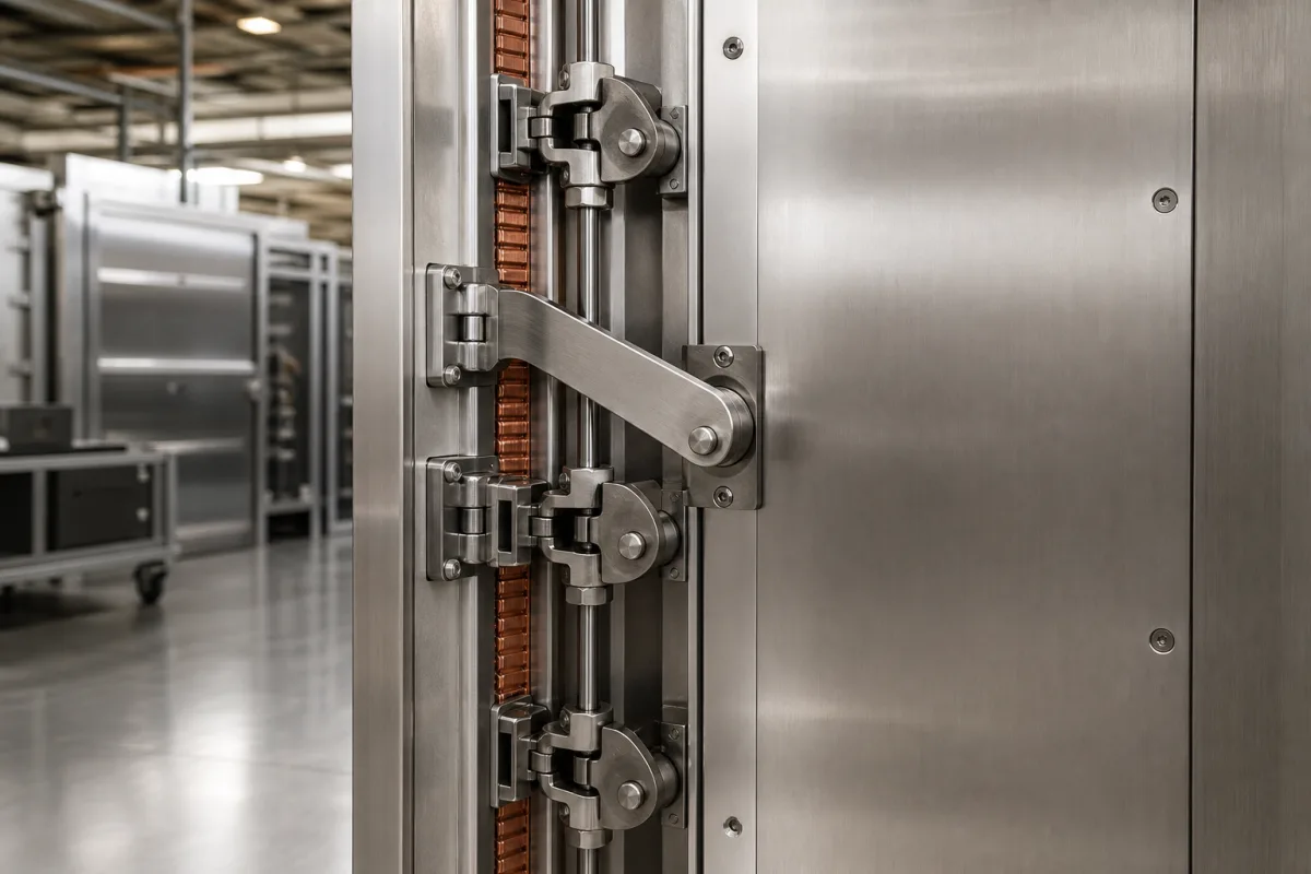
Latching Mechanism in a manufacturing environment
Representative product image. Confirm appearance and specifications with the manufacturer.

Product Specifications

Technical details and manufacturing context for Latching Mechanism

Definition
This latching mechanism is a component designed for RF-shielded access doors, ensuring secure closure while preserving the electromagnetic shielding effectiveness of the enclosure. It operates by drawing the door tightly against the frame, compressing conductive gaskets to create a continuous conductive seal around the perimeter. This action maintains the Faraday cage effect, preventing electromagnetic interference (EMI) leakage. The mechanism typically employs a cam or lever action to apply uniform pressure, ensuring proper gasket compression and metal-to-metal contact where applicable. Materials commonly used include stainless steel, zinc-plated steel, and aluminum alloy, chosen for their durability and conductivity. The latching throw distance, typically 5-15 mm, is a key parameter that determines how far the mechanism pulls the door into the frame, affecting the compression of gaskets and overall shielding performance. This product is intended for use in applications where electromagnetic compatibility is critical, such as in electronic equipment enclosures. It is important to verify model-specific values, including the exact throw distance and material specifications, with the legal manufacturer or supplier to ensure suitability for the intended application. The mechanism does not include any electronic components and relies solely on mechanical action. Proper installation and maintenance are essential to ensure consistent performance over time. Regular inspection for wear, corrosion, or misalignment is recommended to maintain shielding integrity. This product is not a standalone shielding solution but a component that works in conjunction with the door, frame, and gaskets to achieve the desired level of RF shielding.
Working Principle
The latching mechanism uses a cam or lever action to draw the door tightly against the frame. When engaged, it compresses conductive gaskets around the door perimeter, creating a continuous conductive seal. This ensures metal-to-metal contact or proper gasket compression, maintaining the Faraday cage effect and preventing EMI leakage. The mechanism applies uniform pressure to ensure consistent shielding effectiveness across the entire door perimeter.
Common Materials
Stainless Steel, Zinc-plated Steel, Aluminum Alloy
Technical Parameters

What to specify in your RFQ

  • Latching throw distance (typically 5-15mm) - the distance the mechanism pulls the door into the frame in mm

These are the quantities to specify to the manufacturer when sizing or requesting a quote. The manufacturer's own documentation governs the exact figures and applicable standard.

Components / BOM
  • Latch Handle Part
    Manual interface for operating the latching mechanism
    Material: Stainless Steel
  • Cam Mechanism
    Converts rotational handle motion to linear door compression
    Material: Hardened Steel
  • Strike Plate Part
    Receives latch and provides electrical contact surface
    Material: Copper Alloy
  • Spring Return Part
    Ensures positive latching engagement and maintains pressure
    Material: Spring Steel

Applied To / Applications

This component is essential for the following industrial systems and equipment:

Industrial Ecosystem & Supply Chain Structure

Complementary Systems
Downstream Applications
Specialized Tooling

Application Fit & Sizing Matrix

Operational Limits
pressure: 0 to 0.5 bar differential
other spec: RF shielding effectiveness: ≥60 dB @ 1-10 GHz
temperature: -40°C to +85°C
Media Compatibility
✓ EMI/RFI shielded enclosures ✓ Clean room environments ✓ Outdoor telecom cabinets
Unsuitable: High-vibration industrial machinery (exceeds latching stability limits)
Sizing Data Required
  • Door panel thickness (mm)
  • Required shielding attenuation (dB)
  • Door opening force specification (N)

Reliability & Engineering Risk Analysis

Failure Mode & Root Cause
Wear-induced misalignment
Cause: Frictional wear on contact surfaces (e.g., latch hooks, striker plates) leading to improper engagement or excessive play, often accelerated by inadequate lubrication, contamination, or repeated overloading.
Fatigue fracture
Cause: Cyclic stress from repeated latching/unlatching operations causing crack initiation and propagation in high-stress areas (e.g., pivot points, spring attachments), typically due to material defects, improper heat treatment, or design stress concentrations.
Maintenance Indicators
  • Audible grinding, clicking, or squeaking during operation indicating excessive friction or component wear
  • Visual misalignment or incomplete closure (e.g., latch not fully seating, visible gaps) suggesting deformation or wear
Engineering Tips
  • Implement regular lubrication with appropriate anti-wear grease on all moving contact surfaces, following manufacturer specifications for type and interval
  • Conduct periodic alignment checks and torque verification on mounting hardware to prevent stress concentrations and ensure proper engagement geometry

Indicative industry ranges for design and RFQ preparation. Confirm the exact figures and applicable standard with the manufacturer before specifying.

Compliance & Manufacturing Standards

Applicable Standards
ANSI/BHMA A156.13 American National Standard for Mortise Locks and Latches DIN 18251 Building hardware - Single-action locks and latches

Quoted from the published standard.

Manufacturing Precision
  • Latch throw length: +/-0.5mm
  • Latch face flatness: 0.1mm
Quality Inspection
  • Cyclic endurance test (minimum 100,000 cycles)
  • Force measurement test (latch engagement/disengagement force)

Manufacturers of Latching Mechanism

Manufacturer profiles associated with Latching Mechanism.

Sourcing Latching Mechanism from China?
Tell us your specification and target quantity — we will match it against manufacturer records and come back with the factories that fit.
Request manufacturers We manufacture this

Manufacturer listings support early research and capability understanding. They are not certification, ranking, or transaction guarantees.

Share this page
Technical documentation
Request current drawings, revision history, and a signed specification sheet.
Manufacturing capability
Verify equipment lists, process limits, capacity, and representative production evidence.
Inspection readiness
Confirm test methods, calibrated equipment, sampling plans, and traceable reports.
Supplier transparency
Check the legal entity, factory address, ownership, certifications, and direct contacts.

CNFX does not score or rank suppliers. Buyers must verify all claims and documents with the legal manufacturer before ordering.

Supply Chain Compatible Machinery & Devices

Industrial IoT Gateway

The Industrial IoT Gateway is a ruggedized edge computing device designed for industrial environments.

Explore Specs →
Modular Industrial Edge Computing Device

This modular industrial edge computing device is a ruggedized system designed for deployment in harsh industrial environments to perform real-time data processing, analytics, and control functions at the network edge.

Explore Specs →
Industrial Smart Camera Module

The Industrial Smart Camera Module is a compact, self-contained vision processing unit designed for integration into industrial machinery and production lines.

Explore Specs →
Surface Mount Resistor

Passive electronic component for current limiting and voltage division in circuits

Explore Specs →

Frequently Asked Questions

What is the typical latching throw distance for this mechanism?

The latching throw distance is typically 5-15 mm, as specified in the product parameters. This distance determines how far the mechanism pulls the door into the frame, affecting gasket compression and shielding performance. Always verify the exact value for your specific model with the manufacturer.

What materials are available for this latching mechanism?

The materials on file include stainless steel, zinc-plated steel, and aluminum alloy. These materials are selected for their durability and conductivity. The specific material used may affect corrosion resistance and electrical performance, so confirm the material for your application with the supplier.

How does this mechanism maintain RF shielding effectiveness?

The mechanism draws the door tightly against the frame, compressing conductive gaskets to create a continuous conductive seal. This ensures proper gasket compression and metal-to-metal contact, maintaining the Faraday cage effect and preventing electromagnetic interference leakage.

Is this mechanism suitable for all RF-shielded enclosures?

This mechanism is designed for RF-shielded access doors, but suitability depends on specific application requirements such as door size, gasket type, and required shielding effectiveness. Verify compatibility with your enclosure design and consult the manufacturer for guidance.

Data Basis

Editorial classification, named public sources where available, and source-reviewed manufacturer records.

Preliminary Technical Classification
This page supports structured research, RFQ preparation, and supplier evaluation. It does not replace buyer-led supplier qualification, standards review, or technical approval.
Buyer enquiry

Request manufacturing insight for Latching Mechanism

Ask for use case, specification boundaries, supplier type, and RFQ preparation information for this product.

Where it goes
Straight to the CNFX editorial desk, and to the manufacturer if this product is linked to a claimed profile. Nothing is broadcast to a supplier list.
Your details stay here
We do not sell or rent enquiry data, and we do not add you to a mailing list. Used only to answer this request.
No commission, no middleman
CNFX is a directory. We take no cut of any order and never negotiate on a supplier's behalf.
What we don't claim
A listing is not an endorsement. Qualify every supplier and verify every figure yourself before ordering.

Your business information is used only to process this request.

Thank you! Your message has been sent. We'll respond within 1–3 business days.
Sorry, we couldn't send your message. Please try again, or email us at [email protected].

Need to Manufacture Latching Mechanism?

Compare manufacturer profiles with relevant product and process capability.

Previous Product
XY Positioning Stage
Last Product
Get QuotesChat