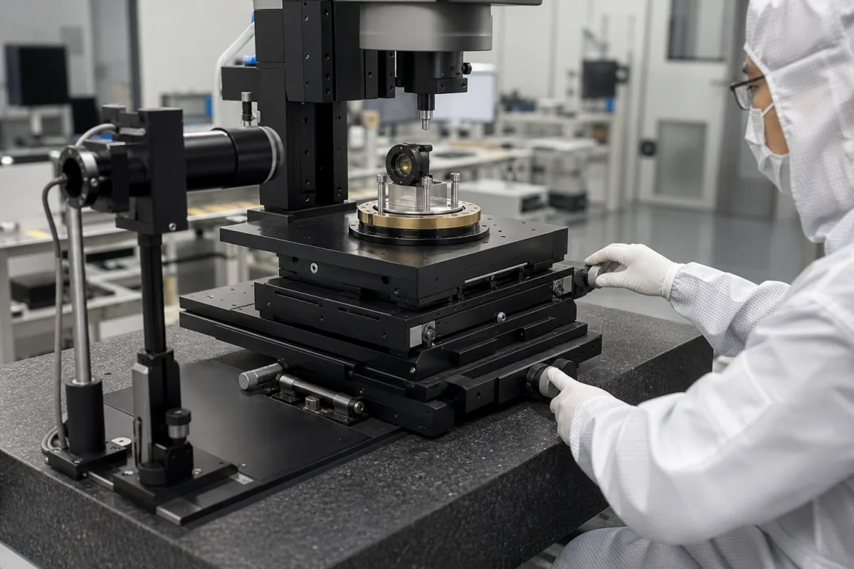
Manual multi-axis alignment stage: XY, Z, rotation and tip-tilt stages stacked and driven by micrometers
Hand-adjusted stack of XY, Z, rotation and tip-tilt stages for aligning a lens, fibre or sample · ±3 to ±6.5 mm linear, ±5° fine rotation, ±2° to ±3° tilt, 1 to 4 kg per stage
Where a lens, a fibre end or a small sample has to be brought onto an optical axis by hand, one way to do it is a stack of small stages: a linear XY stage at the bottom, a vertical stage on it, then a rotation stage and a tip-tilt platform, each moved by its own micrometer. This page is about that hand-adjusted stack — what each layer contributes, how far each one moves, how much it carries, and what changes when the micrometers are replaced by motorized actuators.
Manually adjusted multi-axis alignment assemblies built by stacking compact XY, Z, rotation and tip-tilt (kinematic) stages driven by micrometers, used to align optics, fibres and samples in laboratories, inspection and assembly. Motor-driven XY tables and XYZ stages for automated dispensing, placement and inspection are covered on the XYZ positioning stage page; the general class of manual and motorized linear, rotary and tilt stages on the Precision positioning stages page; single ball-screw axes on the Linear positioning stage (ball screw driven) page; CNC and indexing rotary tables on the Rotary table page; heavy rail-mounted gantries on the Gantry system for heavy loads page.
CNFX editorial research · Sources checked October 12, 2026 · 4 sources
Four stages in one 40 mm stack: steel XY, Z, brass rotation and aluminium tip-tilt
OptoSigma sells a manual six-axis assembly (XYZ, rotation and two tilt axes) built from four catalogue stages, all 40 mm and joined by M3 threads. [1]
The assembly text and the part listing do not quite agree: the description gives the XY stage "a 6.5mm range" and the Z stage "a 3mm range", while the part names read +/-6.5 mm and +/-3 mm. [1] Ask the supplier whether travel is stated as total stroke or as plus-or-minus from centre before relying on either figure.
Editorial calculation: the four list prices add up to 726 + 552 + 333 + 189 = USD 1,800 for the stack at the time of review; prices change and exclude mounting adapters.
Editorial note: the order of the stack decides which motions move the others. With rotation and tilt on top, turning the XY micrometers moves the whole angular sub-assembly without changing its angles, but a tilt adjustment swings the part about the tilt stage's pivot, not about the lens or fibre tip, so the part can walk off the optical axis and need re-centring in XY.
Layer (bottom to top)
OptoSigma part
Construction and drive
Published travel
List price (USD, at review)
XY translation
TSD-402C
40 × 40 mm steel stage on EXC bearings, centre micrometer
Tell the supplier the part to be aligned and its weight, which axes must be adjustable, the required travel and angle on each, the mounting thread or hole pattern, and the height available between the table and the optical axis.
02
Angle and load by size: Edmund Optics tip-tilt stages at ±2° to ±3° and rotary stages at ±5° fine
In Edmund Optics' TECHSPEC manual stages, angular range and load both depend on the platform size, and the largest tip-tilt stage gives up angle for load. [2][3]
The tip-tilt stages are aluminium, tilt in two axes with a kinematic movement and are driven by metric micrometers. [2] The rotary stages have a slide-fit guide, a locking screw, 360° coarse and ±5° total fine rotation by micrometer, and are rated Class 100 (ISO 5) clean-room compatible. [3] OptoSigma's 40 mm rotation stage likewise combines 360° manual rotation with ±5° fine adjustment, and its 40 mm tilt stage gives ±2° where Edmund's 40 mm tip-tilt gives ±3°. [1][2]
Editorial note: in a stack each stage carries the stages above it as well as the part. A 40 mm rotary stage rated 1.5 kg under a tip-tilt stage and a lens mount is carrying both; add the weights of everything above each stage and compare that sum with its rating.
Ask for each angular stage: range, the angle moved per micrometer revolution or division, where the pivot point lies relative to the platform surface, and the load rating for the stack position it will occupy.
03
Replacing the micrometers with actuators: a ±2° tilt, ±2.5° rotation platform at 1.25 µm per step
EKSMA Optics sells the same kind of two-axis angular platform with motorized actuators in place of micrometers. Its 970-0090 (multi-axis tilt platform 6TP116) tilts ±2° out of plane and rotates ±2.5° in plane about a kinematic pivot point, moved by two screws placed side by side. [4]
EKSMA states that the adjustment movements are not calibrated and are uncoupled, and that a manual version and a vacuum version are available. [4] The resolution and repeatability are those of the linear actuators, in micrometres; the datasheet does not convert them into an angle.
Editorial calculation: 0.25 mm pitch ÷ 1.25 µm per full step = 200 full steps per screw revolution, and 1.25 µm ÷ 8 = 0.156 µm at 1/8 step, matching the stated figures. [4]
Editorial note: because the angular movements are not calibrated, a motorized tilt platform like this still needs feedback from the optical signal or an autocollimator to know the actual angle; the motors make the adjustment repeatable and remote, not absolute.
Explore company information and manufacturing capabilities, then discuss the scope of your project with a relevant supplier.
Share this page
Compiled and source-reviewed by the CNFX editorial team.
Each manufacturer above links to the page on that company's own website where the product is listed, with the date we checked it. How we source and review
· Page last updated 13 October 2026
Buyer questions
Which stages make up a manual six-axis alignment stage?
OptoSigma's 40 mm assembly stacks a steel XY stage (±6.5 mm), a Z stage (±3 mm), a brass rotation stage (360°, ±5° fine) and a ±2° two-axis kinematic tilt stage, all micrometer or knob driven. [1]
How much tilt does a manual tip-tilt stage give?
Edmund Optics lists ±3° for its 30, 40 and 70 mm tip-tilt stages and ±2° for the 125 mm size; OptoSigma's 40 mm tilt stage gives ±2°. [2][1]
How much load can a small rotary stage carry?
Edmund Optics rates its manual rotary stages at 1 kg (30 mm), 1.5 kg (40 mm), 3 kg (70 mm) and 5 kg (125 mm). [3]
Can a tilt platform be motorized?
Yes; EKSMA's 970-0090 gives ±2° tilt and ±2.5° rotation with actuators of 0.25 mm lead screw pitch, 1.25 µm full-step resolution and 1 µm repeatability, with uncalibrated, uncoupled movements. [4]
Sources and what still needs a direct check
Sources checked 2026-10-12. The stack, its parts, travel and list prices come from OptoSigma's assembly page; angle and load by size from Edmund Optics' tip-tilt and rotary stage family sheets; the motorized tilt-rotation platform from EKSMA Optics' datasheet.