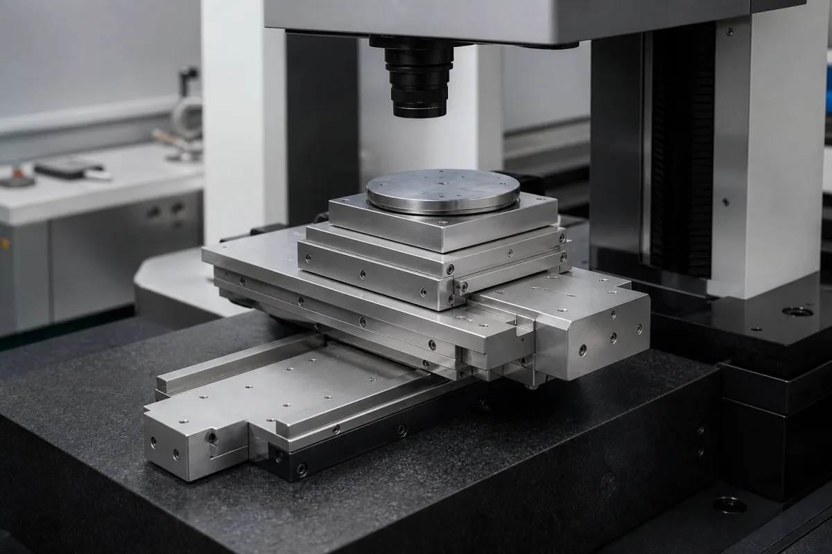
Multi-axis positioning system for optical inspection: stacked, integrated or planar XY axes under the camera, corrected with a 2D error map
Multi-axis positioning systems under inspection optics · Stacked, integrated or planar XY construction and the flatness and pitch/roll it costs at the ends of travel, then a 2D error map from a glass grid plate and camera that corrects orthogonality and screw error
This page covers multi-axis positioning systems built for optical inspection: XY stages, with or without a rotary and a focusing axis, that carry boards, wafers or parts under a camera or microscope on a granite base. Ask three things first: whether the XY axes are stacked, integrated or planar and what that does to flatness across the field, how errors between the axes, above all orthogonality, will be measured and corrected, and which artefact and fit the 2D error map uses.
Multi-axis XY, XY-theta and XYZ positioning systems for optical and camera inspection, including their 2D error mapping. Single positioning stages, their accuracy and repeatability definitions and Abbe error are covered on the Positioning stage page, and XY tables and XYZ stages built from ball-screw, belt or linear-motor modules, with drive sizing and payload, on the XYZ positioning stage page. Gantry robots for handling, machine tool tables, coordinate measuring machines and piezo nanopositioners are outside this page.
CNFX editorial research · Sources checked October 12, 2026 · 4 sources
Stacked, integrated or planar XY: what each does to flatness across the inspection field
PI explains that XY motion can come from stacking two linear stages, which is modular and flexible, but over long travel flatness and pitch/roll errors grow towards the end of travel because the base of the upper axis is unsupported; its flatness measurement on a stacked stage shows the cantilevered, loaded Y axis performing worse than the lower X axis. Integrated XY stages, which it says are at times wrongly called planar, share a central plate as the top of the lower axis and the base of the upper one, giving a lower profile and a wider bearing base that reduces cantilever errors, with the same bearings and drives as stacked stages. Planar XY stages use one reference plane for both axes, based on air bearings, magnetic levitation or flexures, and PI shows air-bearing planar stages reaching flatness of 1 µm and better over hundreds of millimetres. [1]
PI calls flatness especially critical where an optical process must stay in focus, since vertical deviation turns into focus error. [1] Editorial calculation: an orthogonality error of 10 arcseconds between X and Y shifts a point by about 4.8 µm over 100 mm of Y travel, which can exceed the pixel size of the inspection camera; it is one of the errors a 2D map can correct.
Module-built systems sit at the stacked end of this range: Fuyu lists XY tables and XYZ stages from single to three axes and gantry systems, with visual inspection among its application fields. [4]
One reference plane; air bearing, maglev or flexure. [1]
Flatness of 1 µm and better over hundreds of mm. [1]
Give the supplier the part or wafer size, the inspection field and the camera's pixel size, the axes needed (X, Y, theta, focus), the load, the move-and-settle time per image, the accuracy needed across the field, and the base and environment.
02
A 2D error map from a glass grid plate and the camera, fitted point by point
Dover Motion lists the errors that mapping can correct: leadscrew cumulative and periodic error, Abbe error, nut backlash, cosine error and deviation from orthogonality in multi-axis systems. Its mapping station places glass grid plates with 12 µm wide chrome lines every 10 mm, the smaller ones on near-zero-expansion Zerodur, in a tip-tilt-yaw mount on the XY stage under test, which sits on a granite surface plate under a bridge carrying a Z focusing stage, a long-working-distance 100× objective and a machine vision camera; it reports X-Y accuracy improved ten to twenty times over an unmapped stage. [2]
Dover's worked example: a screw stage with 1 µm resolution that moves 100.013 mm for 100,000 steps is commanded 99,987 steps for a true 100 mm, and, assuming linear screw error, 49,994 steps for 50 mm; it notes that thermal expansion limits how much accuracy mapping can add to leadscrew systems. [2] Editorial calculation: 0.013 mm over 100 mm is a scale error of 130 ppm.
Zaber's 2D calibration note, for calibrating XY systems for orthogonality, distortion and stretch of each axis, fits expected against actual grid positions: a biquadratic fit needs at least 3 × 3 = 9 points, and with 5 × 5 = 25 points the code makes a least-squares fit that reduces the error further. [3]
03
Send the inspection field, axes and accuracy together
Paste it into your enquiry below or into an email to a maker, then replace every bracket.
Field: [part or wafer size; camera pixel size]
Axes: [X; Y; theta; focus]
Construction: [stacked; integrated; planar]
Accuracy: [across field; repeatability]
Mapping: [grid plate; interferometer; points]
Cycle: [move-and-settle per image]
1 company lists this product among what they make. Company figures are quoted from each
company's own website; every card states where the relationship came from.
FUYU Technology
Manufacturing site to be confirmed for the order
Lists XY tables and XYZ positioning stages, single to three axes and gantry systems, with visual inspection among its application fields.
Explore company information and manufacturing capabilities, then discuss the scope of your project with a relevant supplier.
Share this page
Compiled and source-reviewed by the CNFX editorial team.
Each manufacturer above links to the page on that company's own website where the product is listed, with the date we checked it. How we source and review
· Page last updated 13 October 2026
Buyer questions
Why do stacked XY stages lose flatness at the ends of travel?
PI explains that the base of the upper axis is unsupported at the extremes, so flatness and pitch/roll errors grow towards the end of long travel. [1]
What can a 2D error map correct?
Dover lists leadscrew cumulative and periodic error, Abbe error, nut backlash, cosine error and deviation from orthogonality, and reports a 10–20× XY accuracy gain. [2]
How many grid points does a 2D calibration need?
Zaber's note says a biquadratic fit needs at least 3 × 3 = 9 points; 5 × 5 = 25 points allow a least-squares fit. [3]
Sources and what still needs a direct check
Sources checked 2026-10-12. PI, Dover Motion and Zaber describe stage designs and calibration from their own practice; Fuyu lists its XY and XYZ stages.