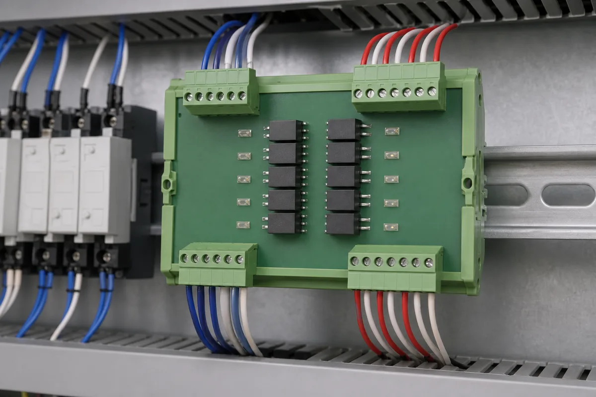
DIN-rail optocoupler isolation board: 8 to 16 isolated channels between PLC or DAQ I/O and field devices
Multi-channel optocoupler boards on a DIN rail between a controller and field wiring · isolation rating, current per channel and per group, and switching speed
An optocoupler board puts a row of optocouplers, status LEDs and terminal blocks on one DIN-rail carrier, so that the signals between a PLC or data-acquisition card and field devices pass through an optical gap rather than a wire. The boards compared here differ in three things: how much voltage the isolation is rated for, how much current each output may switch on its own and when its neighbours are on too, and how fast a channel follows the signal. Data from three boards show the spread.
DIN-rail and panel-mount boards carrying multiple optocoupler channels, fixed or plug-in, with terminals and indicators, used to isolate digital inputs and outputs of PLCs, motion controllers and data-acquisition systems. Single optocoupler and digital-isolator components, with their current transfer ratio and IEC 60747-5-5 ratings, are covered on the Optocoupler / isolator page; photonic optical isolators for lasers and fibre systems, built on Faraday rotators, are outside this page and Faraday rotators are covered on the Faraday rotator page.
CNFX editorial research · Sources checked October 12, 2026 · 3 sources
Isolation: a 4 kV AC test voltage on one board, 60 V DC on another
Phoenix Contact's UMK-8 OM-R/MF/MKDS/P (2972699) is an 8-channel carrier with plug-in sockets for solid-state relays or digital I/O modules, a yellow LED per channel, an integrated fuse and screw terminals; it lists a test voltage of 4 kV AC and cites DIN VDE 0110b, group C, for 250 V DC. [1] bmcm's OI16 isolates 16 digital inputs and 16 outputs of a data-acquisition system by one optocoupler per line, but states its galvanic isolation as 60 V DC to VDE and that the board is suitable only for extra-low voltages. [2]
The Phoenix sheet states a test voltage, and the Leadshine listing states no isolation voltage. [1][3] The request should state the highest voltage present on the field side and ask for the board's rated working isolation voltage, not only its test voltage.
Optocoupler isolation; no voltage given in the listing [3]
—
The bmcm board is a measurement accessory for extra-low voltage; it is not suited to isolating mains-referenced field circuits.
02
0.25 A per output but 0.8 A per group: what eight channels can drive at once
bmcm rates each OI16 output, a high-side driver, at 0.25 A, but limits the total to 0.8 A per 8-bit port at 25 °C, with a voltage drop of about 1.5 V; inputs accept 7–35 V DC, read above 4.5 V as high, draw up to 10 mA and tolerate 60 V DC for 10 s. [2] Leadshine's PM-0016-P gives 0.5 A on a single channel but 0.3 A per channel when more than one is used, with one shared COM terminal for each 8 outputs, short-circuit and over-current protection and an LED per channel. [3] Phoenix Contact lists a limiting continuous current of 4 A and a typical input current of 30 mA, both dependent on the fitted optocoupler. [1]
Editorial calculation: with the OI16 on a 24 V supply, the 1.5 V drop leaves about 22.5 V at the load, and a 0.25 A output dissipates about 0.375 W in its driver.
Switching speed: 0.05 ms and 10 kHz on the OI16, 20 µs / 50 µs on the PM-0016-P
bmcm gives an optocoupler speed of about 0.05 ms and a bandwidth of 0 to 10 kHz for the OI16. [2] Leadshine's listing for the PM-0016-P gives 20 µs/50 µs as its response figures without further breakdown. [3] The Phoenix UMK-8 sheet does not give a switching speed; its datasheet points to the user documentation and to the plug-in module chosen. [1]
State the fastest signal the board must pass, in Hz or as a minimum pulse width, alongside the voltage and current per channel.
04
Data for an optocoupler board enquiry
Paste it into your enquiry below or into an email to a maker, then replace every bracket.
Channels: [number of inputs and outputs; NPN or PNP; COM grouping]
Signals: [input voltage and current; output voltage and current per channel; all channels on at once?]
Isolation: [highest field-side voltage; working isolation voltage required; test voltage]
Speed: [maximum frequency or minimum pulse width]
Mounting: [DIN rail; connector type to the controller; terminal type to the field]
Explore company information and manufacturing capabilities, then discuss the scope of your project with a relevant supplier.
Share this page
Compiled and source-reviewed by the CNFX editorial team.
Each manufacturer above links to the page on that company's own website where the product is listed, with the date we checked it. How we source and review
· Page last updated 13 October 2026
Buyer questions
Is the isolation on an optocoupler board always rated for mains?
No. Phoenix Contact lists a 4 kV AC test voltage for its UMK-8 carrier, while bmcm states 60 V DC isolation for its OI16 and limits it to extra-low voltages. [1][2]
Can every output carry its full rating at the same time?
Not on the boards shown. bmcm allows 0.25 A per output but 0.8 A per 8-bit port; Leadshine gives 0.5 A for a single channel and 0.3 A each when more than one is on. [2][3]
How fast does an optocoupler board switch?
bmcm states about 0.05 ms and 0–10 kHz for the OI16; Leadshine lists 20 µs/50 µs for the PM-0016-P. [2][3]
How much current do the inputs draw?
Phoenix Contact gives 30 mA typical per channel for the UMK-8, depending on the optocoupler fitted; the OI16 inputs draw up to 10 mA. [1][2]
Sources and what still needs a direct check
Sources checked 2026-10-12. Isolation, current and speed figures come from Phoenix Contact's UMK-8 OM-R/MF/MKDS/P data sheet, bmcm's OI16 manual and Leadshine's PM-0016-P listing. Values apply to the boards named.