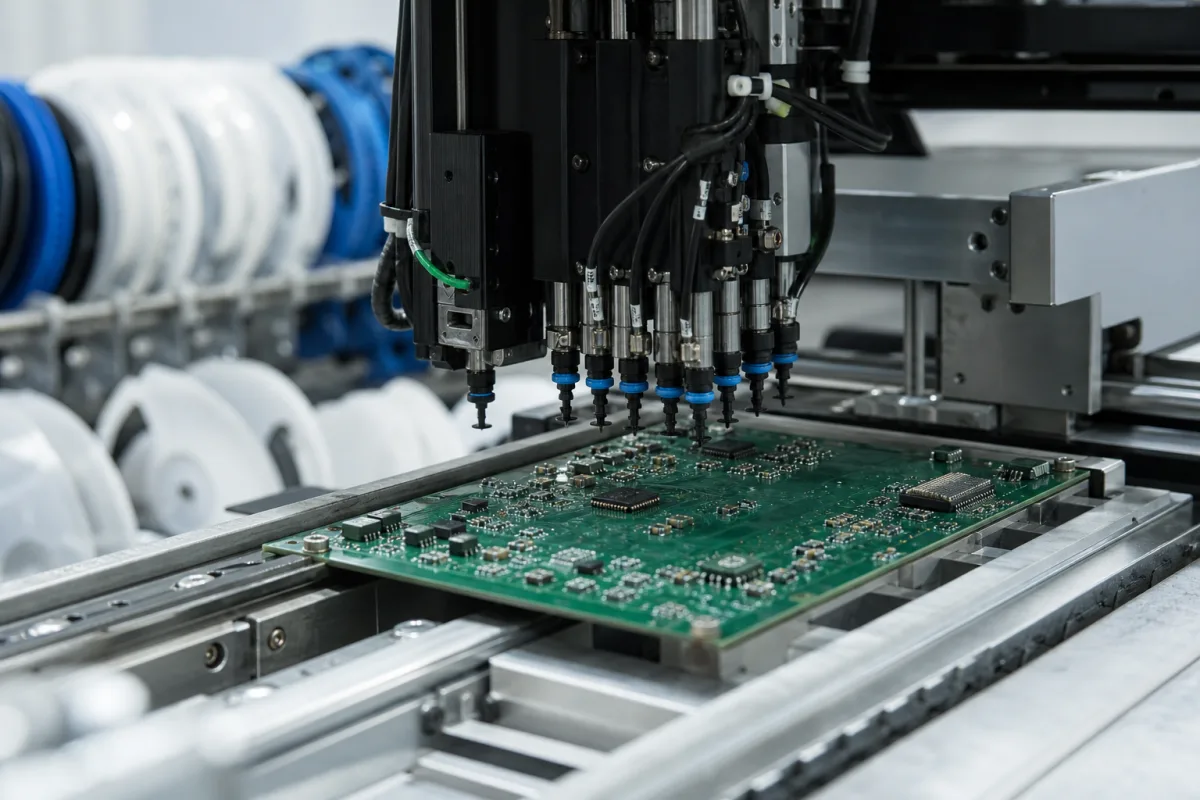
SMT pick-and-place heads · Speed versus component range by head type, accuracy and its statistical basis, nozzle care
A placement head is the part of an SMT pick-and-place machine that picks electronic components from feeders with vacuum nozzles, turns and centres them, and places them on the printed circuit board. Ask three things first: which component sizes and heights the head can handle, what placement speed it reaches and under what conditions, and what accuracy it holds and on which statistical basis.
Placement heads for SMT pick-and-place machines — multi-nozzle rotary (revolver), in-line and single or twin heads — and their nozzles, as supplied on new machines or as head options. Feeders, stencil printers, reflow ovens and through-hole inserters are outside this page.
CNFX editorial research · Sources checked October 11, 2026 · 4 sources
Yamaha's YRM20 specification shows the trade-off between head types. Its RM head handles components from 0201 mm to 12 × 12 mm and up to 6.5 mm tall at 115,000 CPH with two head units; its HM head takes 0201 mm to 100 × 55 mm and 15 mm tall at 98,000 CPH; and its FM head takes 03015 mm to 100 × 55 mm and 30 mm tall at 35,000 CPH. Each figure halves with one head unit, and all are under Yamaha's optimised conditions. [1]
ASMPT's SIPLACE X lists three heads: the CP20 for components from 0201 metric to 8.2 × 8.2 × 4 mm at up to 43,000 cph; the CPP from 01005 to 50 × 40 mm and 15.5 mm tall at up to 23,500 cph; and the Twin head from 0201 metric to 200 × 150 × 25 mm at up to 5,500 cph. ASMPT notes that the CPP head lets one line stay balanced through product changes without head changes. [2]
Editorial calculation: a board with 600 placements takes about 600 / 115,000 h ≈ 19 s on the YRM20's RM head pair but 600 / 35,000 h ≈ 62 s on its FM head pair at the rated optimum. Real rates are lower once board transfer, nozzle changes and feeder layout are included. The placement count is an assumed example. [1]
Give the supplier your component list with the smallest and largest package sizes and heights, placements per board and boards per hour, board size and thickness, feeder count and types, nozzle types needed, required accuracy and its basis, and whether the machine must handle fine-pitch or odd-form parts.
02
Ask how the software assigns nozzles and parts to each head
Rated speed assumes the head's nozzles are used well. A Harbin Institute of Technology patent, US 10,785,901 B2, describes a beam-type single-gantry mounter whose head assembly carries six placement heads, with an auto nozzle changer (ANC). When two or more heads share the same picking coordinate they can pick at once; it calls two heads picking together two simultaneous pickups, and states that n simultaneous pickups save the time of n − 1 picking actions. Simultaneous pickup needs feeders that occupy the same number of slots and have identical X and Y pickup offsets. Its method assigns nozzles and components to heads to minimise pick-and-place cycles, nozzle replacements and trips to the ANC, and to maximise simultaneous pickups, and the patent reports overall production efficiency gains of up to 20.9% in its tests. [4]
Editorial note: Yamaha's and ASMPT's rated speeds are stated under their own conditions, so run your own component list through each supplier's optimisation software and compare the resulting cycle count and nozzle changes as well as the rated cph. [1][2]
Yamaha states YRM20 mounting accuracy as ±0.025 mm at Cpk ≥ 1.0 for its RM and HM heads and ±0.035 mm at Cpk ≥ 1.0 for its FM head. [1] ASMPT states accuracy as up to ±34 µm @ 3σ for the CP20 head, ±30 µm @ 3σ for the CPP and ±26 µm @ 3σ for the Twin head, and up to 25 µm for the machine. [2]
Yamaha describes automatic nozzle care: a blow station cleans the air channel, a side camera checks the nozzle exterior and vibration is checked, while a dashboard analyses causes of pickup errors and suggests feeder or nozzle actions. [1] ASMPT lists closed-loop nozzle management, smart nozzles with unique IDs and a laser sensor that detects components on the nozzle. [2] NeoDen's range runs from 2 to 8 heads, with its 8-head model rated up to 20,000 CPH and 0.01 mm placement accuracy. [3]
Editorial note: a Cpk of 1.0 means the ±3σ spread of placements just fits within the stated tolerance, so '±25 µm at Cpk ≥ 1.0' and '±25 µm @ 3σ' describe similar capability; a statement without either basis cannot be compared. Ask every supplier for accuracy, speed and the test conditions on the same basis.
04
Desktop and floor machines with 2 to 8 heads from the linked supplier
The listing reviewed offers desktop and floor pick-and-place machines with 2, 4, 6 or 8 heads; ask for the head's component range, speed under stated conditions and accuracy basis.
05
Nozzle turret, Z and theta drives, part sensing and nozzle care on a placement head
Part
Role
Fix in the order
Nozzle holder or turret
Holds the nozzles, which are tracked by ID. [1][2]
Head count, cph, accuracy basis, part size and Z stroke for a placement-head order
Speed and accuracy rows mix Yamaha's Cpk figures with ASMPT's 3σ figures; keep the basis next to each number when you compare quotations, and ask for the head's Z stroke against your tallest part.
1 company lists this product among what they make. Company figures are quoted from each
company's own website; every card states where the relationship came from.
Zhejiang NeoDen Technology Co., Ltd
Manufacturing site to be confirmed for the order
Lists pick-and-place machines with 2, 4, 6 and 8 placement heads, up to 20,000 CPH.
Explore company information and manufacturing capabilities, then discuss the scope of your project with a relevant supplier.
Share this page
Compiled and source-reviewed by the CNFX editorial team.
Each manufacturer above links to the page on that company's own website where the product is listed, with the date we checked it. How we source and review
· Page last updated 13 October 2026
Buyer questions
Why do placement heads have different speeds?
Heads for small parts run faster: Yamaha's RM head reaches 115,000 CPH for parts up to 12 × 12 mm, its FM head 35,000 CPH for parts up to 30 mm tall. [1]
How accurate are SMT placement heads?
Yamaha states ±0.025 mm at Cpk ≥ 1.0; ASMPT states ±26 to ±34 µm @ 3σ depending on head. [1][2]
What is the largest component a placement head can place?
ASMPT's Twin head places parts up to 200 × 150 × 25 mm. [2]
Are rated CPH figures achieved in production?
Yamaha's figures are under its optimised conditions; ask for rates under your own board and feeder setup. [1]
How does simultaneous pickup speed up a placement head?
Harbin Institute of Technology's US 10,785,901 B2 states that n heads picking at once save the time of n − 1 picking actions, if the feeders share slot width and pickup offsets. [4]
Sources and what still needs a direct check
Sources checked 2026-10-11. Yamaha and ASMPT are placement machine makers publishing their own head data; NeoDen is the linked supplier; the Harbin Institute of Technology patent describes head task assignment on a six-head machine. Rates and accuracies are those makers' figures under their stated conditions.