Editorial Technical Reference

Z-Axis Actuator

This page explains how Z-Axis Actuator is classified within Machinery and Equipment Manufacturing. Technical values and manufacturer relationships are research references; confirm the current specification and supplier evidence for each order.

Technical Definition & Core Assembly

Linear motion component that provides vertical movement along the Z-axis in a gantry system
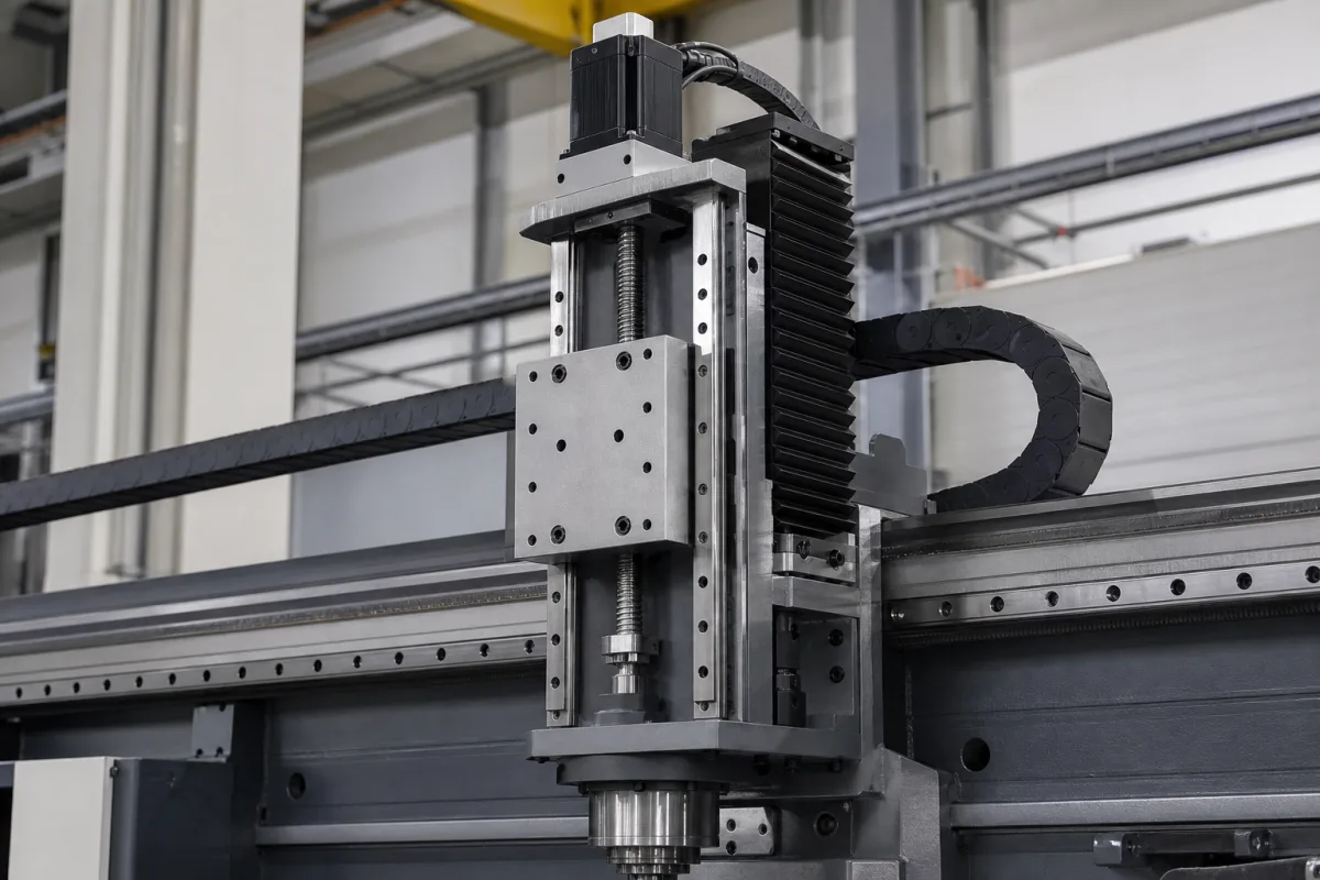
Representative product image. Confirm appearance and specifications with the manufacturer.

Product Specifications

Technical details and manufacturing context for Z-Axis Actuator

Definition
A precision mechanical component within a gantry system responsible for controlled vertical (Z-axis) movement, typically used for positioning, lifting, or applying force in automated manufacturing and material handling applications. This actuator converts rotational motion from a motor (servo, stepper, or other) into precise linear motion through mechanical transmission elements such as ball screws, lead screws, or linear motors, with position feedback from encoders or sensors. It is designed for integration into gantry systems where vertical positioning accuracy and repeatability are critical. The actuator is available in a range of configurations to suit different load and stroke requirements. Standard stroke lengths range from 100 to 600 mm, with custom strokes available. Maximum payload capacity is between 50 and 200 kg, depending on the model and configuration. Positioning repeatability is ±0.02 to ±0.05 mm, tested to ISO 230-2, with higher accuracy available on request. Maximum speed ranges from 0.5 to 1.5 m/s, depending on load and motor selection. Motor power options are 0.4 to 3.0 kW, with servo or stepper motors. Supply voltage is three-phase, 220–380 V AC, per IEC 60038. Operating temperature range is -10°C to 50°C; below -10°C, seals may fail. Protection class is IP54 to IP65, with IP65 recommended for dusty environments, per IEC 60529. Lead screw diameter is 16 to 32 mm (ball screw or trapezoidal), per ISO 2901. Lead screw lead is 5 to 20 mm, determining speed and resolution. Guide rail width is 15 to 35 mm, per ISO 12090-1. Overall dimensions (L×W×H) range from 500×200×150 mm to 1500×300×250 mm, depending on stroke and load. Weight without motor is 15 to 80 kg. Materials used include aluminum alloy, steel, and engineering plastics. This component is intended for use in automated manufacturing and material handling systems. Always verify model-specific values and standards with the legal manufacturer or supplier before procurement.
Working Principle
The actuator operates by converting rotational motion from an electric motor into linear motion along the vertical Z-axis. This is achieved through mechanical transmission elements such as a ball screw or lead screw, or directly via a linear motor. The motor, which can be a servo or stepper type, drives the screw, causing a nut attached to the moving carriage to translate along the screw's axis. Position feedback is provided by encoders or sensors, enabling precise control of the carriage's position. The system is designed to handle vertical loads and provide repeatable positioning within specified tolerances. The choice of transmission element affects speed, resolution, and load capacity. The actuator is typically integrated into a gantry system, where it is mounted to move a tool or payload vertically. Control signals from a CNC or PLC coordinate the actuator's movement with other axes. The mechanical design includes guide rails to ensure smooth and accurate motion, and the housing protects internal components from environmental factors. The actuator's performance is influenced by factors such as load, speed, and duty cycle, which must be considered during selection.
Common Materials
Aluminum alloy, Steel, Engineering plastics
Technical Parameters
ParameterTypical rangeNotes & selection driver
Stroke Length100–600 mmCustom strokes available
Maximum Payload50–200 kgVertical load capacity
Positioning Repeatability±0.02–±0.05 mmHigher accuracy availableISO 230-2
Maximum Speed0.5–1.5 m/sDepends on load and motor
Motor Power0.4–3.0 kWServo or stepper
Supply Voltage220–380 V ACThree-phaseIEC 60038
Operating Temperature-10–50 °CBelow -10°C seals may fail
Protection ClassIP54–IP65IP65 for dusty environmentsIEC 60529
Lead Screw Diameter16–32 mmBall screw or trapezoidalISO 2901
Lead Screw Lead5–20 mmDetermines speed and resolution
Guide Rail Width15–35 mmLinear guide typeISO 12090-1
Overall Dimensions (L×W×H)500×200×150–1500×300×250 mmDepends on stroke and load
Weight15–80 kgWithout motor

Ranges are indicative industry figures for RFQ preparation, not a supplier commitment. Confirm every value and standard with the legal manufacturer before ordering.

Components / BOM
  • Motor
    Provides rotational power for motion conversion
    Material: Steel, copper, magnets
  • Lead Screw/Ball Screw
    Converts rotational motion to linear motion
    Material: Steel, stainless steel
  • Linear Guide
    Provides smooth, low-friction linear motion guidance
    Material: Steel, aluminum
  • Encoder/Sensor
    Provides position feedback for closed-loop control
    Material: Electronic components, plastics

Applied To / Applications

This component is essential for the following industrial systems and equipment:

Industrial Ecosystem & Supply Chain Structure

Complementary Systems
Downstream Applications
Specialized Tooling

Application Fit & Sizing Matrix

Operational Limits
pressure: 0 to 10 bar
other spec: Max velocity: 2 m/s, Max acceleration: 10 m/s², Stroke length: 50-2000 mm
temperature: -10°C to +50°C
Media Compatibility
✓ Clean air environments ✓ Dry inert gases ✓ Non-corrosive industrial atmospheres
Unsuitable: High concentration abrasive slurry environments
Sizing Data Required
  • Required stroke length (mm)
  • Maximum load capacity (kg)
  • Required positioning accuracy (±mm)

Reliability & Engineering Risk Analysis

Failure Mode & Root Cause
Ball Screw Wear and Backlash
Cause: Insufficient lubrication, contamination ingress, or excessive axial loads leading to premature wear of ball screw threads and recirculating components, resulting in positioning inaccuracies and increased backlash.
Linear Guide/Bearing Failure
Cause: Misalignment during installation, shock loads, or particulate contamination causing brinelling, spalling, or seizure of linear bearings, leading to increased friction, vibration, and potential binding.
Maintenance Indicators
  • Audible grinding, clicking, or scraping noises during operation indicating mechanical interference or bearing failure.
  • Visible metal shavings or discolored grease around the actuator housing or on wipers, suggesting internal wear or overheating.
Engineering Tips
  • Implement a strict, condition-based lubrication regimen using manufacturer-specified grease, and install protective bellows or seals to prevent contamination ingress.
  • Perform regular alignment checks and vibration analysis to detect early-stage bearing wear or imbalance, and ensure mounting surfaces are within flatness and parallelism tolerances.

Indicative industry ranges for design and RFQ preparation. Confirm the exact figures and applicable standard with the manufacturer before specifying.

Compliance & Manufacturing Standards

Applicable Standards
ISO 10791-7:2020 (Test conditions for machining centres - Accuracy of finished test pieces) ANSI B5.54-2005 (Methods for Performance Evaluation of Computer Numerically Controlled Machining Centers) DIN 8602-1 (Machine tools - Acceptance conditions for machining centres - Part 1: Geometric tests for machines with horizontal spindle)

Quoted from the published standard.

Manufacturing Precision
  • Positioning Accuracy: +/-0.005mm over full travel
  • Repeatability: +/-0.002mm
Quality Inspection
  • Laser Interferometer Calibration (for positioning accuracy verification)
  • Ball Bar Test (for circular interpolation and dynamic accuracy assessment)

Manufacturers of Z-Axis Actuator

Manufacturer profiles associated with Z-Axis Actuator.

Sourcing Z-Axis Actuator from China?
Tell us your specification and target quantity — we will match it against manufacturer records and come back with the factories that fit.
Request manufacturers We manufacture this

Manufacturer listings support early research and capability understanding. They are not certification, ranking, or transaction guarantees.

Technical documentation
Request current drawings, revision history, and a signed specification sheet.
Manufacturing capability
Verify equipment lists, process limits, capacity, and representative production evidence.
Inspection readiness
Confirm test methods, calibrated equipment, sampling plans, and traceable reports.
Supplier transparency
Check the legal entity, factory address, ownership, certifications, and direct contacts.

CNFX does not score or rank suppliers. Buyers must verify all claims and documents with the legal manufacturer before ordering.

Supply Chain Compatible Machinery & Devices

Hydraulic Press

Industrial machine using hydraulic pressure to compress, form, or assemble materials

Explore Specs →
Heavy-Duty CNC Plasma Cutting Machine

The Heavy-Duty CNC Plasma Cutting Machine is a standalone industrial device designed for cutting conductive metals such as steel, stainless steel, aluminum, and copper alloys.

Explore Specs →
Automated Powder Coating System

Integrated industrial system for applying dry powder coatings to metal substrates.

Explore Specs →
Centrifugal Pump Impeller

The centrifugal pump impeller is a critical rotating component that converts mechanical energy from the motor into kinetic energy in fluid systems.

Explore Specs →

Frequently Asked Questions

What is the maximum payload of this Z-axis actuator?

The maximum payload is between 50 and 200 kg, depending on the specific model and configuration. The exact value should be confirmed with the manufacturer for your application.

What is the positioning repeatability?

Positioning repeatability is ±0.02 to ±0.05 mm, tested to ISO 230-2. Higher accuracy may be available on request, but must be verified with the supplier.

What are the available stroke lengths?

Standard stroke lengths range from 100 to 600 mm, with custom strokes available. The required stroke should be specified based on your application needs.

What protection class is available?

The protection class is IP54 to IP65, per IEC 60529. IP65 is recommended for dusty environments. Confirm the required rating with the manufacturer.

Data Basis

Editorial classification, named public sources where available, and source-reviewed manufacturer records.

Preliminary Technical Classification
This page supports structured research, RFQ preparation, and supplier evaluation. It does not replace buyer-led supplier qualification, standards review, or technical approval.
Buyer enquiry

Request manufacturing insight for Z-Axis Actuator

Ask for use case, specification boundaries, supplier type, and RFQ preparation information for this product.

Where it goes
Straight to the CNFX editorial desk, and to the manufacturer if this product is linked to a claimed profile. Nothing is broadcast to a supplier list.
Your details stay here
We do not sell or rent enquiry data, and we do not add you to a mailing list. Used only to answer this request.
No commission, no middleman
CNFX is a directory. We take no cut of any order and never negotiate on a supplier's behalf.
What we don't claim
A listing is not an endorsement. Qualify every supplier and verify every figure yourself before ordering.

Your business information is used only to process this request.

Thank you! Your message has been sent. We'll respond within 1–3 business days.
Sorry, we couldn't send your message. Please try again, or email us at contact@cnfx.com.

Need to Manufacture Z-Axis Actuator?

Compare manufacturer profiles with relevant product and process capability.

Previous Product
Z-axis Ram/Spindle
Last Product
Get QuotesChat